3
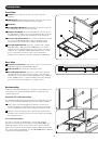
Refer to the installation diagrams below as you perform these steps.
Note:
Make sure that the power to the computer or KVM switch being connected to the console is powered off before proceeding with the installation.
1
Connect the Black VGA connector on the included cable kit to the VGA port on the back of the console.
2
Connect the Blue VGA connector on the other side of the cable kit to the VGA port on the back of your computer or KVM switch.
3
Connect the PS/2 keyboard and mouse connectors, on the same side of the cable kit as the Blue VGA connector, to the PS/2 keyboard
and mouse ports on the back of your computer or KVM switch. If you have a computer or KVM switch with USB connectors, connect the
PS/2 keyboard and mouse connectors on the cable kit to the connectors on the included PS/2 to USB adapter, and then plug the USB
connector on the adapter into an available USB port on your computer or KVM switch.
Note:
Although KVM switches will contain two USB console ports for keyboard and mouse, you can plug the single USB connector on the adapter into
either port.
4
Remove the USB covers from each of the Pass-Through USB ports. Connect the Pass-Through USB port on the back of the console to a
USB port on a computer or KVM switch using a USB A Male/Male cable, such as Tripp Lite’s UR020-Series. Connect a USB device to the
Pass-Through USB port on the front of the console.
Note:
The Pass-Through ports do not connect to the internal components in the console (the keyboard, the touchpad or the console).
5
Connect the power cord to the socket on the back of the console, and then plug it into a Tripp Lite Surge Protector, Power Distribution
Unit (PDU), or Uninterruptible Power Supply (UPS).
6
Power on the connected computer or KVM switch.
7
Turn on the LCD screen by pressing the On/Off button on the control panel of the built-in monitor.
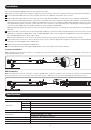
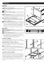
Computer Installation
Note:
The diagram below shows the connection of a computer with PS/2 keyboard and mouse ports. To connect to a USB computer, use the PS/2 to USB
adapter provided with the console.
Function
Specification
Connectors
Console
1 x HD-15 female
Cable Kit
1 x HD-15 male to 1 x HD-15 male, 2 x PS/2 male
Power
1 x IEC-60320-C14 AC socket (100-240V~, 50/60Hz)
Comm.
1 x USB (Type A to Type A)
LCD Resolution
1366 x 768; DDC2B
Environment
Operating Temperature: 32°- 104° F
Storage Temperature: -4°- 140° F
Humidity: 0 - 80% RH Noncondensing
Housing
Metal
Weight
36 pounds
Dimensions (L x W x H)
28 x 19 x 1.7 inches
Installation
Specifications
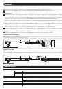
KVM Installation
Note:
The diagram below shows the connection of a B042-016 KVM switch, using PS/2 connections. The console ports of different model KVM switches may
be located elsewhere on the unit. To connect to the USB console port on a KVM switch, use the PS/2 to USB adapter provided with the console.
Computer Installation
KVM Installation
1
1
2
2
3
3
5
5
4
4