Model UT231: OPERATING MANUAL
20
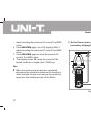
To avoid damages to the Meter or harms to you, do
you measure higher than AC voltage 600V rms and
AC current 1000A rms.
Warning
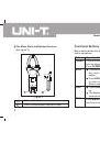
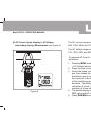
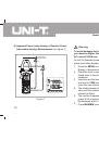
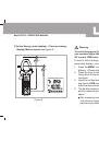
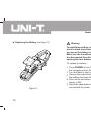
To test for Apparent power (main display) + Reactive
power (secondary display), connect the Meter as follows:
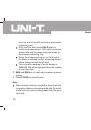
Press the
MENU
to select Power factor (main
display) + Phase angle (secondary display) range.
Press the lever to open the transformer jaw, and
clamp them to the power source or the tested
conductor.
Insert the red test lead to
V
input terminal and black
test lead to
COM
input terminal and connect them
to tbe live wire and neutrual wire of the tested circuit.
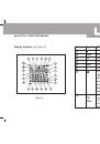
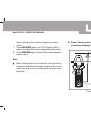
The double display shows the power factor value
and the phase angle value of the measured object.
When the power factor value is negative, it means
the loading is capacItive.
When the power factor value is positive, it means
the loading is inductive.
MAX
and
MIN
are not valid when measuring power
1.
2.
3.
4.
5.
6.
7.
factor.
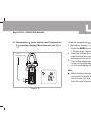
When testing has been completed, disconnect the
connection between the testing leads and the circuit
under test and remove testing leads from the input
terminals.
Note