21
22
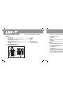
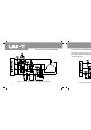
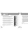
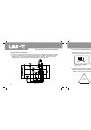
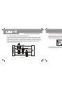
As shown in Figure 7-6, please press
key to measure
total three-phase power. Current measured power of the 3rd
phase location also shall be calculated and saved.
Figure 7-6
Figure
Figure
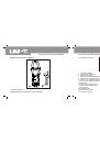
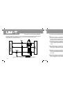
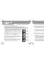
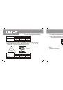
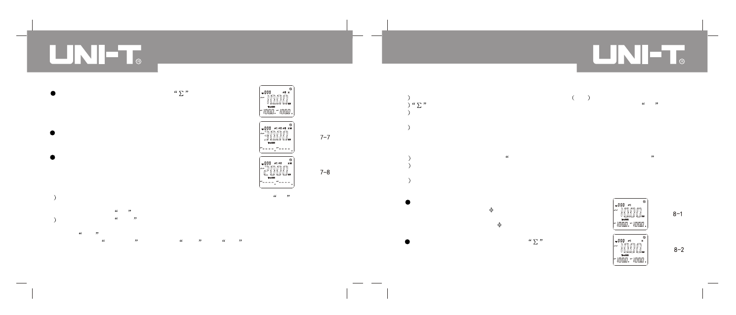
As shown in Figure 7-7, total three-phase active power
can be displayed by pressing SELECT key finally.
Measurement operation of the 1st and 2nd phase locations is
the same as that of three-phase four-wire system. As shown in
Figure 7-8, total three-phase active power can be displayed by
pressing SELECT key after tripping the 3rd phase location of
measurement.
5
The maximum range is 600kW for single-phase active power to display
OL
symbol if
exceeding the range. The maximum range is 1,800kW for total three-phase active power.
It also will display
OL
symbol if exceeding the range.
6
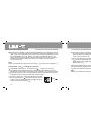
Display will show
MAX
symbol by pressing MAX/MIN key so as to display the maximum
active power, voltage and current during measurement. Please press MAX/MIN key to
show
MIN
symbol on LCD and display the minimum active power during measurement.
Please press
MAX/MIN
key so that
MAX
and
MIN
symbols flicker together. It
can display current value and record the maximum value and the minimum value at the
same time during measurement. Please press the key for a long time to exit the
maximum/minimum value mode.
Note:
1
Please do not measure AC voltage of more than 600
v.r.s
and AC current of 1000A( v.r.s).
2
ke y do es no t eff ect wi thout sig nal inp
ut or du ring sin gle-phase dis play of O L
sym bol.
3
Only current measurement value can be calculated and saved. The maximum value and
the minimum value cannot be calculated or saved.
4
Total power cannot be measured until under active power, apparent power and inactive
power gears.
7.2 Apparent power (kWA)+Voltage(V)+Current (A)
1
Please press MENU to select
Apparent power (kWA)+Voltage (V)+Current (A) gear;
2
Jaw shall be fixed to measured conduits in corresponding phase locations. That is, user
shall measure a certain phase of three-phase circuit so that jaw is on corresponding conduit.
3
Please refer to Figure 4, 5 & 6 of UT240 manual for wiring of three-phase four-wire system,
three-phase three-wire system or single-phase two-wire system.
Figure
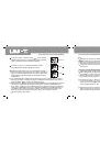
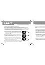
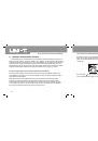
As shown in Figure 8-2, please press
key to measure
total three-phase power. Current measured power of the 1st
phase location also shall be calculated and saved.
As shown in Figure 8-1, please press SELECT key to select
the 1st phase location of
1 for three-phase four-wire
system of load. It can display apparent power, voltage and
current of phase location of
1.
Figure
UT241/242/243 OPERATING MANUAL
UT241/242/243 OPERATING MANUAL