29
30
1
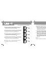
Press MENU to select gear of
Phase location angle (
)+ Voltage (V)+ Current (A)
;
2
Jaw shall be fixed to measured conduits in corresponding phase locations. That is, user
shall measure a certain phase of three-phase circuit so that jaw is on corresponding conduit.
3
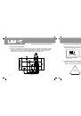
Please refer to Figure 4, 5 & 6 of UT240 manual for wiring of three-phase four-wire system,
three-phase three-wire system or single-phase two-wire system.
4
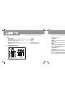
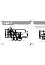
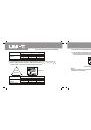
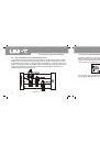
As shown in Figure 11-1, please press SELECT key to select
the 1st phase location of
1 for three-phase four-wire system
of load. It also can display apparent power, voltage and current
of phase location of
1.
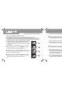
7.5 Phase location angle (
)+Voltage (V)+Current (A)
Figure
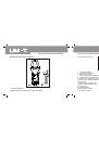
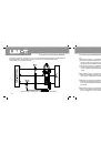
Please press SELECT key to select the 2nd phase location of
2 shown in Figure 11-2. It also can display apparent power,
voltage and current of phase location of
2.
Figure
Figure
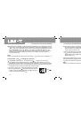
Please press SELECT key to select the 3rd phase location of
2 shown in Figure 11-3. It also can display apparent power,
voltage and current of phase location of
3.
Measurement operation of the 1st and 2nd phase locations is the same as that of three-phase
four-wire system after tripping the 3rd phase location of measurement.
5
There is no measurement function of the maximum/minimum value for this function gear.
Note:
Please do not measure AC voltage of more than 600V
r.m.s
and AC current of 1000A
r.m.s
.
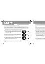
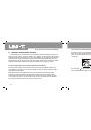
7.6 Voltage frequency (Hz)+Voltage (V)+Current (A)
1
Press MENU key to select gear of
frequency + voltage + current
;
2
Jaw shall be fixed to measured conduits in corresponding phase locations. That is, user
shall measure a certain phase of three-phase circuit so that jaw is on corresponding conduit.
3
Please refer to Figure 4, 5 & 6 of UT240 manual for wiring of three-phase four-wire system,
three-phase three-wire system or single-phase two-wire system.
4
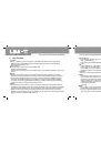
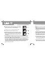
As shown in Figure 12-1, please press SELECT key to select
the 1st phase location of
1 for three-phase four-wire system
of load. It also can display apparent power, voltage and
current of phase location of
1.
Figure
Please press SELECT key to select the 2nd phase location
of
2 shown in Figure 12-2. It also can display apparent
frequency, voltage and current of phase location of 2.
Figure
UT241/242/243 OPERATING MANUAL
UT241/242/243 OPERATING MANUAL