35
36
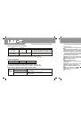
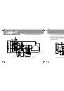
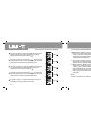
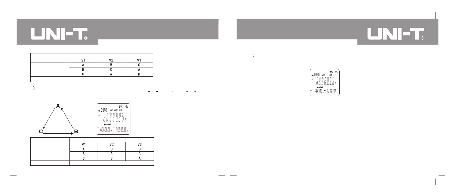
Phase location
A, B & C
Detection result
Positive sequence
Jack
3
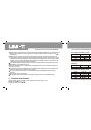
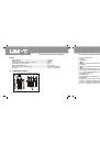
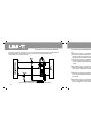
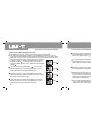
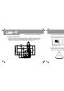
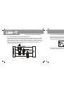
Inverted sequence layout is shown in following figure. As shown in Figure 19, LCD can
display inverted sequence detection result when connecting
V1
,
V2
and
V3
jacks to Phase A, B & C if three-phase voltage exceeds 50V.
Phase location
A, B & C
Detection result
Jack
Inverted sequence
Inverted
sequence
Figure 19
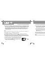
4
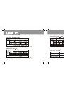
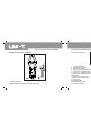
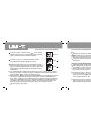
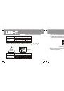
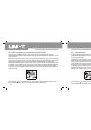
LCD will display default phase detection result if certain phase of voltage is less than 50V or
without signal for three-phase four-wire system load. As shown in Figure 20, symbols of
corresponding phases will not be displayed on LCD.
Figure 20
Default phase of the 2nd phase
Note:
Detection voltage range of positive and inverted sequence is 30V~500V. Voltage range without
default phase is 50V~500V.
UT241/242/243 OPERATING MANUAL
UT241/242/243 OPERATING MANUAL