37
38
8
Harmonic measurement function
Press HARM key for circulation switchover of following harmonic measurement functions. 3
frequency modes, namely, AUTO , 50Hz
a
nd 60Hz
c an b
e s elected f or a
ll h
armonic
measurement functions respectively.U
ser c an p
ress H
ARM k ey f or a
l ong t ime t o a
lter f requency
mode temporarily during measurement. (Instrument will restore default mode after power-off.)
Default frequency mode also can be set under setup mode. (Please refer to Clause 9.3: Default
frequency mode setup for SE3 harmonic function for difference of 3 frequency modes.)
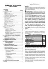
8.1 Total voltage harmonics for full wave distortion rate (V THD-R
It will measure and display effective value of total harmonics of single-phase voltage to full
wave distortion rate, harmonic order and corresponding orders of harmonic voltage for load of
three-phase four-wire system.
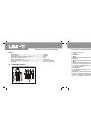
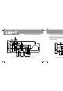
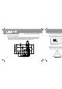
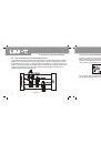
Measurement steps: Press HARM key to enter into measurement mode of total voltage
harmonics to total wave distortion rate firstly after bootstrap and connect voltage signal of
measured phase to voltage input end of instrument by probe and connect zero wire to COM
end. As shown in Figure 14, connect phase wire to any port of V1/V2/V3 and press SELECT
key so that measurement port can be consistent with input port.
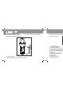
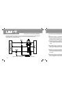
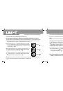
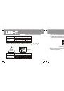
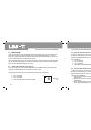
As shown in Figure 21, LCD will display current harmonic order (with auxiliary display in left
lower corner), total voltage harmonics for full wave distortion rate (with auxiliary display in right
lower corner) and effective value of harmonic voltage (with main display in the middle)
respectively.
Figure 21
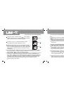
User can press
key to increase harmonic order or press
key to reduce harmonic order. It
also will display effective value of various voltage harmonic components correspondingly.
UT241/242/243 OPERATING MANUAL
UT241/242/243 OPERATING MANUAL