ELEC
SIGNALLING SYSTEM
7-19
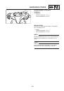
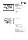
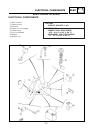
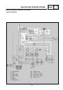
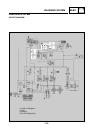
4. Connections
• Check the connections throughout the sig-
nalling system.
• See the “ELECTRICAL DIAGRAM”section
Check the conditions for each signalling sys-
tem circuit.
Consult the “CHECKING SIGNALLING SYS-
TEM” section.
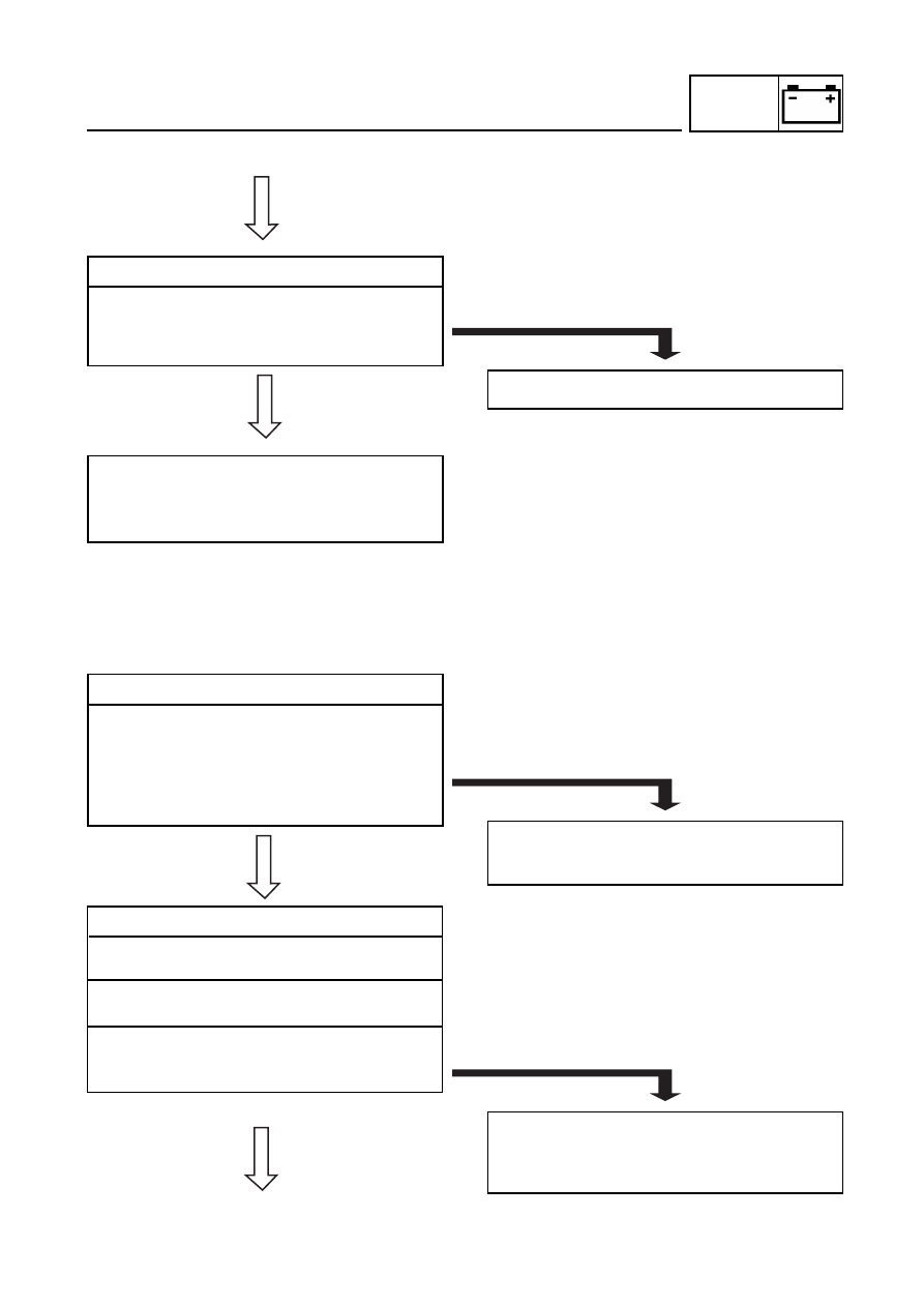
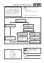
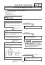
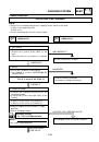
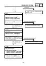
CHECKING SIGNALLING SYSTEM
1. Horn does not operate
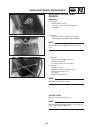
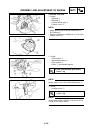
1.“HORN” switch.
• Disconnect the coupler of the handlebar
switch (left) from the installation and horn
cable.
• Check the switch component for continuity
between “Black
and Red
”.
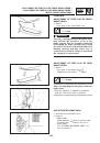
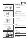
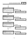
2. Voltage
• Connect the pocket tester (20 V DC) on the
horn cable.
Cable (+) of the tester
Brown
Cable (–) of tester
Frame earth
• Place the main switch on “ON”
• Check if there is a voltage (12 V) in the
brown cable of the horn terminal.
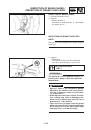
SATISFIES
THE SPECIFIED
VALUE (12 V)
CORRECT
CORRECT
BAD CONNECTION
Repair
INCORRECT
The “HORN” switch is defective, change the
handlebar switch (left).
OUTSIDE SPECIFIED VALUE
The connection circuit from the main switch
to the horn terminal is defective, repair.
 1
1
 2
2
 3
3
 4
4
 5
5
 6
6
 7
7
 8
8
 9
9
 10
10
 11
11
 12
12
 13
13
 14
14
 15
15
 16
16
 17
17
 18
18
 19
19
 20
20
 21
21
 22
22
 23
23
 24
24
 25
25
 26
26
 27
27
 28
28
 29
29
 30
30
 31
31
 32
32
 33
33
 34
34
 35
35
 36
36
 37
37
 38
38
 39
39
 40
40
 41
41
 42
42
 43
43
 44
44
 45
45
 46
46
 47
47
 48
48
 49
49
 50
50
 51
51
 52
52
 53
53
 54
54
 55
55
 56
56
 57
57
 58
58
 59
59
 60
60
 61
61
 62
62
 63
63
 64
64
 65
65
 66
66
 67
67
 68
68
 69
69
 70
70
 71
71
 72
72
 73
73
 74
74
 75
75
 76
76
 77
77
 78
78
 79
79
 80
80
 81
81
 82
82
 83
83
 84
84
 85
85
 86
86
 87
87
 88
88
 89
89
 90
90
 91
91
 92
92
 93
93
 94
94
 95
95
 96
96
 97
97
 98
98
 99
99
 100
100
 101
101
 102
102
 103
103
 104
104
 105
105
 106
106
 107
107
 108
108
 109
109
 110
110
 111
111
 112
112
 113
113
 114
114
 115
115
 116
116
 117
117
 118
118
 119
119
 120
120
 121
121
 122
122
 123
123
 124
124
 125
125
 126
126
 127
127
 128
128
 129
129
 130
130
 131
131
 132
132
 133
133
 134
134
 135
135
 136
136
 137
137
 138
138
 139
139
 140
140
 141
141
 142
142
 143
143
 144
144
 145
145
 146
146
 147
147
 148
148
 149
149
 150
150
 151
151
 152
152
 153
153
 154
154
 155
155
 156
156
 157
157
 158
158
 159
159
 160
160
 161
161
Инструкции и руководства похожие на YAMAHA NEOS 50 YN50 (2002)


Другие инструкции и руководства из категории Мотоцикл