ELEC
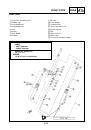
SIGNALLING SYSTEM
7-24
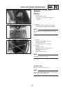
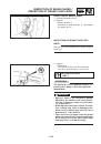
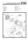
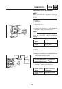
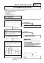
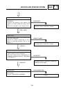
• Place main switch on “*”
• Check if there is a voltage (12 V) on the
“Gray” cable of the bulb holder connector
SATISFIES THE
SPECIFIED VALUE
(12 V)
The circuit is in good condition.
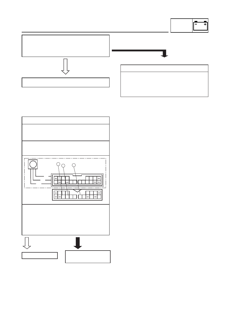
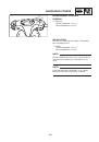
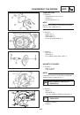
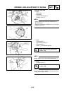
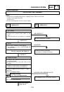
5. The speedometer fails to come on.
1. Voltage
• Connect the pocket tester (DC 20 V) to the
multi-function meter socket coupler (wire
harness side) as shown.
Positive tester probe
red/yellow
Negative tester probe
black/yellow
L
Y
Br
Ch Dg
R
B
Gy
GR
BY
Sb
G
LG
Dg Ch
L
GR
Y
Gy
R
Br
B
BY
Sb
G
RY
RY
LG
R
Y
/
L
G
/
B
Y
/
1
3
2
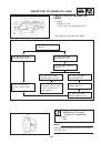
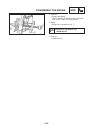
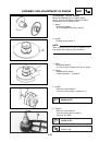
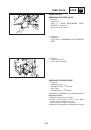
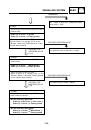
• Set the main switch to “ON”.
• Measure the voltage (DC 12 V) of
red/yellow
on the multi-function meter
coupler (wire harness side).
• Is the voltage within specification?
Replace the speed
sensor.
YES
NO
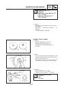
OUTSIDE SPECIFIED VALUE
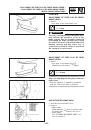
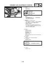
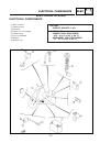
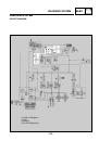
4. Connections
• Check the connections throughout the sig-
nalling system.
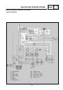
See the “ELECTRICAL DIAGRAM”
section.
This circuit is OK.
 1
1
 2
2
 3
3
 4
4
 5
5
 6
6
 7
7
 8
8
 9
9
 10
10
 11
11
 12
12
 13
13
 14
14
 15
15
 16
16
 17
17
 18
18
 19
19
 20
20
 21
21
 22
22
 23
23
 24
24
 25
25
 26
26
 27
27
 28
28
 29
29
 30
30
 31
31
 32
32
 33
33
 34
34
 35
35
 36
36
 37
37
 38
38
 39
39
 40
40
 41
41
 42
42
 43
43
 44
44
 45
45
 46
46
 47
47
 48
48
 49
49
 50
50
 51
51
 52
52
 53
53
 54
54
 55
55
 56
56
 57
57
 58
58
 59
59
 60
60
 61
61
 62
62
 63
63
 64
64
 65
65
 66
66
 67
67
 68
68
 69
69
 70
70
 71
71
 72
72
 73
73
 74
74
 75
75
 76
76
 77
77
 78
78
 79
79
 80
80
 81
81
 82
82
 83
83
 84
84
 85
85
 86
86
 87
87
 88
88
 89
89
 90
90
 91
91
 92
92
 93
93
 94
94
 95
95
 96
96
 97
97
 98
98
 99
99
 100
100
 101
101
 102
102
 103
103
 104
104
 105
105
 106
106
 107
107
 108
108
 109
109
 110
110
 111
111
 112
112
 113
113
 114
114
 115
115
 116
116
 117
117
 118
118
 119
119
 120
120
 121
121
 122
122
 123
123
 124
124
 125
125
 126
126
 127
127
 128
128
 129
129
 130
130
 131
131
 132
132
 133
133
 134
134
 135
135
 136
136
 137
137
 138
138
 139
139
 140
140
 141
141
 142
142
 143
143
 144
144
 145
145
 146
146
 147
147
 148
148
 149
149
 150
150
 151
151
 152
152
 153
153
 154
154
 155
155
 156
156
 157
157
 158
158
 159
159
 160
160
 161
161


