ENGLISH
DESCRIPTION
The hood may be in the filtering or the ducting version.
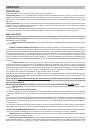
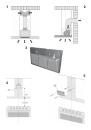
Filtering version
(Fig. 1): The hood aspirates the kitchen air saturated with fumes and odours, purifies it through
the grease filters and charcoal filter and returns clean air into the room. For constant efficiency, the charcoal filter must
be replaced periodically. The charcoal filter is not supplied.
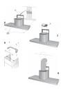
Ducting version
(Fig. 2): The hood aspirates the kitchen air saturated with fumes and odours, passes it through the
grease filters and expels it to the outside through an outlet pipe. With this version the charcoal filter is not required. Decide
from the outset on the type of installation (filtering or ducting). For greater efficiency, we recommend you install the hood
in the ducting version (if possible).
INSTALLATION
ATTENTION: Two persons are required for proper installation; the unit should be installed by a qualified operator.
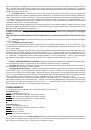
Remove the grease filters before proceeding with the assembly instructions. This will make the appliance easier to handle.
1.
Removal of grease filters
: Fig. 3: push the stop towards the rear of the appliance and turn the filter outwards.
INSTALLATION IN DUCTING VERSION
:
Before fixing, the outlet pipe for air evacuation to the outside must be installed.
Use an outlet pipe with: – minimum indispensable length; – minimum possible bends (maximum angle of bend: 90°); – certified
material (according to the State); – an as smooth as possible inside. It is also advisable to avoid any drastic changes
in pipe cross-section (recommended diameter: 150 mm). For air evacuation to the outside, follow all the other instructions
given on the “Warnings” sheet. Prepare the power supply within the telescopic chimney (for the electrical connection, follow
all the other instructions on the “Warnings” sheet).
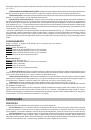
2.
Fixing to the wall:
Draw a line on the wall in vertical line with your hob. Mark the first 2 holes to be drilled in the
wall, respecting the distances indicated in Fig. 4. Drill the 2 holes and fit the screw anchors provided. As already specified
on the “Warnings” sheet, bear in mind that the distance between the lower edge of the hood and the hob must be min.
650 mm. Fix the metal bracket (A) to the wall using the 2 holes just drilled (Fig. 5); the screws for fixing the bracket are
provided. Use the 2 cut-out triangles on the bracket to position it exactly along the vertical axis of the hood. Hang the
hood on the bracket (Fig. 6). Adjust the horizontal position moving the hood to the right or left so that it is aligned with
the wall units. If you also need to adjust the hood in height, operate on the adjusting screws (B) provided.
Once adjusted, finally fix the hood with a further 4 screws (D): Mark the 4 holes to be drilled on the wall, unhook the
hood and drill the holes marked (8 mm diameter); then use the screw anchors and the screws provided for final fixing.
FOR CORRECT FUNCTIONING, THE HOOD MUST BE FIXED USING ALL FOUR SCREWS (D)!
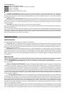
3.
Flange assembly:
set the flange (E) over the motor and press slightly (Fig. 7).
4.
Fixing the telescopic flues:
4a - Adjust the width of the support bracket (D) of the telescopic flue by means of the screws (E) as shown in Fig.8; then,
by means of the screw anchors and screws (F) provided, fix the bracket to the ceiling in such a way that it is positioned
along the axis with your hood.
4b - Connect the air outlet pipe to the air vent of the hood. - Use a flexible pipe and lock it to the air vent of the hood
with a metal hose clamp - Fig. 9 (pipe and clamp are not provided). - For exhaust hoods, turn the upper flue over so that
the air exhaust grid is in the lower section (Fig. 10).
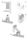
4c - Plug in the hood. Insert the extension flues setting them on the hood; extend the upper flue to the ceiling and secure
with the 2 screws (H) - Fig. 11.
INSTALLATION IN FILTERING VERSION
:
Prepare the power supply within the telescopic flues (for the electrical
connection, follow all the other instructions on the “Warnings” sheet).
Fixing to the wall:
for fixing to the wall refer to the instructions for the ducting version (see points 2 and 3), then
continue with the instructions below.
Fixing the telescopic flues:
- Adjust the width of the support bracket (D) of the telescopic flue by means of the screws
(E) as shown in Fig. 8. - Then, by means of the screw anchors and screws (F) provided, fix the bracket to the ceiling in
such a way that it is positioned along the axis with your hood. - Mount the flange on the hood in correspondence to the
air outlet point (Fig. 12). – Take the air baffle and fit a flexible pipe to it (125 mm diameter) locking it with a metal hose
clamp (pipe and clamps are not provided). Fit the air baffle to the upper flue (Fig. 13) with 4 screws.
- Connect the flexible pipe to the flange on the air vent (Fig. 14). - Plug in the hood. Insert the extension flues setting
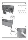
them on the hood; extend the upper flue to the ceiling and secure with the 2 screws H (Fig. 11). - Install the charcoal
filter fitting the two filter clips in their housings (Fig. 15) and turning the filter upward.
OPERATION
Depending on the model, the unit is equipped with the following controls:
Controls shown in Fig.16:
Button A: light button.
Button B: first speed motor ON/OFF button.