Инструкция для Freggia HA631VGTB, HR750VGTAN, HA640VB, HA640VW, HR750VGTCH, HA640VGX, HA640VGTB, HA640VGTW, HA640VX, HA750VGTX, HA640VGTX, HA631VGTX, HA631VGTW, HA750VGTB

16
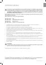
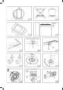
INSTRUCTIONS FOR THE INSTALLER
• ELECTRIC CONNECTION
The connection to the electric grid must be carried out by qualified personnel and in conformity with the regulations
in force.
The voltage of the electric system must correspond to the value indicated in the label under the appliance. Make
sure that the electric system is provided with an effective ground connction in compliance with the regulations and
provisions of the law.
Grounding is compulsory.
This device must be at a suitable opening distance from the contacts in order to allow the entire disconnection in case
of overvoltage category
III
, in accordance with installation rules.
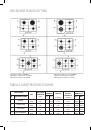
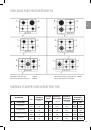
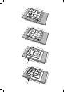
GAS TRANSFORMATIONS AND ADJUSTMENTS
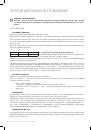
• REPLACING THE NOZZLES
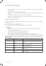
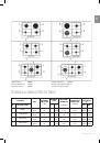
If the equipment is adjusted for a type of gas that is different from the one available, it is necessary to replace the
burner nozzles.
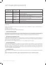
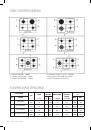
The choice of the nozzles to replace must be made according to the table of the “technical characteristics” as enclosed.
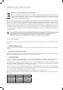
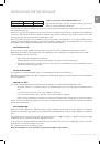
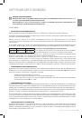
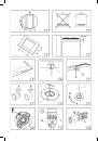
Act as follows:
•
Remove the racks and burners.
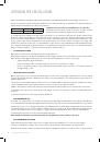
•
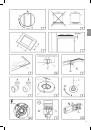
By means of a straight spanner L, unscrew the nozzle U (fig.8) and substitute it with the corresponding one.
•
Tighten the nozzle strongly.
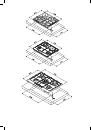
• ADJUSTING THE BURNERS
The lowest flame point must always be properly adjusted and the flame must remain on even if there is an abrupt shift
from the maximum to the minimum position.
If this is not so, it is necessary to adjust the lowest flame point as follows:
•
start the burner up
•
turn the tap up to the minimum position (small flame)
•
remove the knob from the tap rod
•
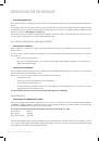
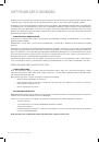
introduce a flat-tip screwdriver in the hole F of the tap (fig. 9-9/A) and turn the by-pass screw up to a proper
adjustment of the lowest flame point.
As regards G30 gas burners, the by-pass screw must be tightened completely.
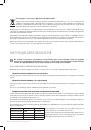
MAINTENANCE
• REPLACING THE POWER SUPPLY CABLE
If the power supply cable should be replaced, it is necessary to use a cable with a section of 3x0.75mm2, type H05VV-F
or H05RR-F, complying with the regulations in force for the hob with gas burners. For the hob with electric plates and
power under 1500W 3x1mm2 power cable should be used.
The connection to the terminal board must be effected as shown in fig. 10 - 10/A:
brown cable L
(phase)
blue cable N
(neutral)
green-yellow cable (ground)
The manufacturing firm refuses all responsibility for any possible imprecision in this booklet, due to misprints or clerical
errors. It reserves the right to make all the changes that it will consider necessary in its own products, without effecting
the essential characteristics of functionality and safety.
INSTRUCTIONS FOR THE INSTALLER