u
Carefully detach the cover panel
Fig. 5 (12)
.
u
Turn the middle turn hinge
Fig. 5 (13)
with the washer
Fig. 5 (14)
through 180° and screw it firmly into place on the
new hinge side (with 4 Nm).
u
Turn the cover panel
Fig. 5 (12)
through 180° and snap it
into place again on the new handle side.
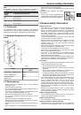
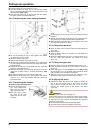
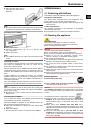
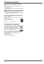
4.3.4 Transferring the lower bearing elements
Fig. 6
u
Lift out the bearing pin
Fig. 6 (22)
together with washer
Fig. 6 (23)
and foot
Fig. 6 (24)
.
u
Lift off the stopper
Fig. 6 (21)
.
u
Unscrew
Fig. 6 (26)
the turn hinge
Fig. 6 (25)
.
u
Unscrew
Fig. 6 (29)
the bearing element
Fig. 6 (28)
, transfer
it to the opposite location hole of the turn hinge and screw it
firmly into place.
u
Carefully lift off the cover on the handle side
Fig. 6 (27)
and
transfer it to the opposite side.
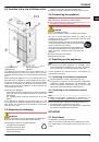
u
Screw the turn hinge
Fig. 6 (25)
firmly into place on the new
hinge side, possibly using a cordless screwdriver (with
4 Nm).
u
Re-insert the stopper
Fig. 6 (21)
into the other hole.
u
Re-insert the bearing pin
Fig. 6 (22)
together with washer
and foot. In so doing, pay attention that the locating lug
points backwards
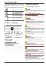
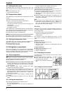
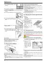
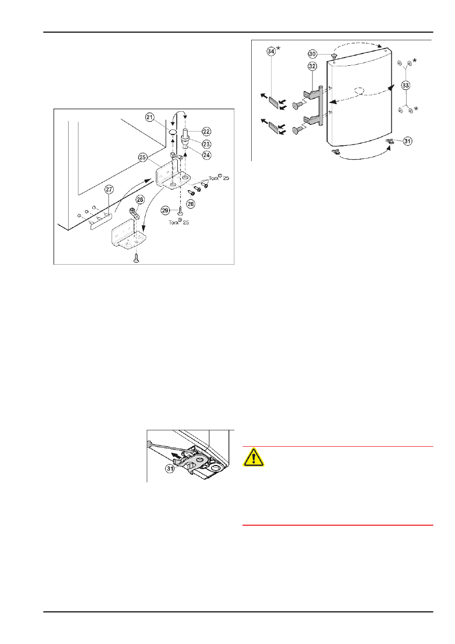
4.3.5 Transferring the handles
On both the upper and lower door:
u
Transfer the spring clamp
Fig. 7 (31)
: Depress the
latch nose and pull the
spring clamp off over it.
u
Slide the spring clamp
into place on the new
hinge side until it clicks
into place.
Fig. 7
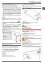
Fig. 8
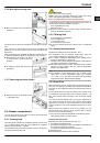
u
Lift the stopper
Fig. 8 (30)
out of the door bearing bush and
transfer it.
u
Detach door handle
Fig. 8 (32)
, stopper
Fig. 8 (33)
and pres-
sure plates
Fig. 8 (34)
and transfer to the opposite side.
u
When fitting the pressure plates on the opposite side, make
sure they snap properly into place*
4.3.6 Fitting the lower door
u
Place the lower door from above onto the lower bearing pin
Fig. 6 (22)
.
u
Close the door.
u
Place the plastic cap
Fig. 5 (10)
back onto the middle turn
hinge
Fig. 5 (13)
.
u
Place the middle bearing pin
Fig. 5 (11)
in the lower door, on
the new hinge side, through the middle turn hinge
Fig. 5 (13)
.
4.3.7 Fitting the upper door
u
Place the upper door on the middle bearing pin
Fig. 5 (11)
.
u
Insert the upper turn hinge
Fig. 4 (3)
in the door on the new
hinge side.
u
Screw the upper turn hinge firmly into place (with 4 Nm)
(2x Torx® 25)
Fig. 4 (4)
. Possibly make preliminary holes
with a bradawl or use a cordless screwdriver.
u
Apply the cover
Fig. 4 (1)
and cover
Fig. 4 (2)
to the oppo-
site side from the outside and snap them into place.
4.3.8 Aligning the doors
u
If necessary, align the doors to the appliance housing by
way of the two oblong holes in the bottom turn hinge
Fig. 6 (25)
and middle turn hinge
Fig. 5 (13)
. To do so,
unscrew the middle screw in the bottom turn hinge
Fig. 6 (25)
.
WARNING
Risk of injury due to the door dropping out!
If the bearing parts are not screwed into place firmly enough,
the door may drop out. This may lead to severe injuries. What
is more, the door may not close and therefore the appliance
may fail to cool properly.
u
Screw the turn hinges firmly into place with 4 Nm.
u
Check all of the screws and retighten if necessary.
Putting into operation
6