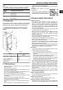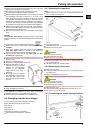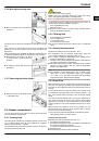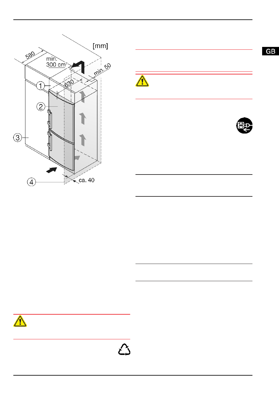
4.4 Insertion into a row of kitchen units
Fig. 9
(1) Stack cabinet
(3) Kitchen cabinet
(2) Appliance
(4) Wall
The appliance can be inserted into a row of kitchen units. To
match the appliance
Fig. 9 (2)
to the height of the row of units,
a suitable stack cabinet
Fig. 9 (1)
can be fitted above the appli-
ance.
When inserting the appliance into a row of kitchen units (max.
depth 580 mm), the appliance can be installed directly next to
the kitchen unit
Fig. 9 (3)
. The appliance door projects relative
to the front of the kitchen unit by 34 mm at the side and by
50 mm in the middle of the appliance. It can be opened and
closed perfectly as a result.
Important for the ventilation:
-
At the back of the stack cabinet there has to be a ventilation
duct of at least 50 mm depth throughout the width of the
stack cabinet.
-
The ventilation space under the ceiling has to be at least
300 cm
2
.
If the appliance is installed with the hinges next to a wall
Fig. 9 (4)
, the distance between appliance and wall has to be at
least 40 mm. This corresponds to the projection of the handle
when the door is open.
4.5 Disposing of packaging
WARNING
Danger of suffocation due to packing material and plastic film!
u
Do not allow children to play with packing material.
The packaging is made of recyclable materials:
-
corrugated board/cardboard
-
expanded polystyrene parts
-
polythene bags and sheets
-
polypropylene straps
-
nailed wooden frame with polyethylene panel*
u
Take the packaging material to an official collecting point.
4.6 Connecting the appliance
NOTICE
Risk of damage to the electronic control system!
u
Do not use stand-alone inverters (conversion of d.c. to a.c./
three-phase) or energy saving plugs.
WARNING
Fire and overheating hazard!
u
Do not use extension cables or multiple socket outlets.
The type of current (alternating current) and voltage at the
installation site have to conform with the data on the type plate
(see Appliance at a glance).
Connect the appliance only with a properly installed
socket outlet with earthing contact. The socket outlet
must be fused with 10 A or higher.
It must be easily accessible so that the appliance can
be quickly disconnected from the supply in an emer-
gency. It must be outside the area of the rear of the
appliance.
u
Check the electrical connection.
u
Plug in the power plug.
4.7 Switching on the appliance
Note
u
To switch on the entire appliance it is necessary only to
switch on the freezer compartment. In so doing, the refriger-
ator compartment is automatically switched on as well.
Put the appliance into operation about 2 hours before first
loading food to be frozen.
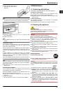
4.7.1 Switching on the freezer compartment
u
PressOn/Off button, freezer compartment
Fig. 3 (9)
.
w
The appliance is switched on. The refrigerator compartment
temperature display indicates the set temperature. The
freezer compartment temperature display and the alarm
button flash until the temperature is sufficiently low.
4.7.2 Switching on the refrigerator compart-
ment
Note
u
When the refrigerator compartment is switched on, the
freezer compartment is automatically switched on as well.
u
Press On/Off button, refrigerator compartment
Fig. 3 (1)
.
w
The interior light is on when the door is open.
w
The temperature display shines. Refrigerator compartment
and freezer compartment are switched on.
5 Control
5.1 Door alarm
For refrigerator and freezer compartment
If the door is open longer then 60 s, the audible alarm sounds.
The audible alarm is automatically silenced when the door is
closed.
Control
7