20
RSX-1057
Surround Sound Receiver
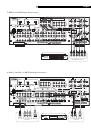
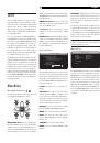
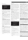
To use the remote turn on feature, connect
one of the RSX-1057’s 12V TRIG OUT jacks to
the 12 volt trigger input of a Rotel amplifier,
using a cable with mono 3.5 mm mini-plugs
on both ends. The +12 V DC signal appears
at the “tip” connector.
REM IN Jacks
Two 3.5 mm mini-jacks (labeled ZONE and
EXT) receive command codes from an in-
dustry-standard infrared receivers (Xantech,
etc.), used when the IR signals from a hand
held remote control cannot reach the front
panel IR sensor.
EXT:
The EXT jack is used with an outboard
IR receiver to duplicate the front panel IR
sensor. This feature is useful when the unit
is installed in a cabinet and the front panel
sensor is blocked or when IR signals need to
be relayed to other components.
ZONE:
The ZONE jack is used with IR repeater
systems to receiver signals from IR control sys-
tems in remote location. For example, remote
control signals sent to the ZONE REM IN con-
trol the ZONE 2 features of the RSX-1057 and
can be relayed to other components.
Consult your authorized Rotel dealer for
information on external receivers and the
proper wiring of a 3.5 mm mini-plugs to fit
the REM IN jacks.
NOTE
:
The IR signals from the EXT REMOTE
IN and ZONE REMOTE IN jacks can be re-
layed to source components using external
IR emitters or hard-wired connections from
the IR OUT jacks. See the following section
for additional information.
IR OUT Jacks
The IR OUT 1 & 2 jacks send IR signals re-
ceived at the ZONE REM IN or the EXT REM
IN jacks to an infrared blaster or emitter
placed in front of a source component’s IR
sensor. In addition, the IR OUT can be hard-
wired to Rotel CD players, DVD players, or
tuners with a compatible connector.
These outputs are used to allow IR signals
from Zone 2 to be sent to the source com-
ponents, or to pass along IR signals from a
remote in the main room when the sensors
on the source components are blocked by
installation in a cabinet.
See your authorized Rotel dealer for informa-
tion on IR emitters and repeater systems.
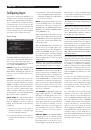
Computer I/O
The RSX-1057 can be operated from a com-
puter with audio system control software
from third-party developers. This control is
accomplished by sending operating codes
from the computer via a hard-wired RS-232
serial connection. In addition, the RSX-1057
can be updated using special software
from Rotel.
The COMPUTER I/O input provides the nec-
essary network connections on the rear pan-
el. It accepts standard RJ-45 8-pin modular
plugs, such as those commonly used in 10-
BaseT UTP Ethernet cabling.
For additional information on the connections,
cabling, software, and operating codes for
computer control or updating of the RSX-1057,
contact your authorized Rotel dealer.
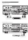
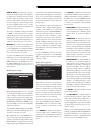
Making Connections
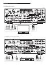
CD Player
See Figure 10
Connect the left and right analog outputs
from the CD player to the AUDIO IN jacks
labeled CD (left and right).
Optional:
Connect the digital output of the
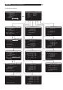
CD player to any of the Optical or Coax dig-
ital inputs on the RSX-1057. Use the INPUT
SETUP screen to assign that digital input to
the CD source.
There are no video connections for a CD
Player.
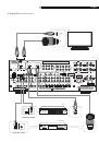
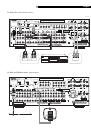
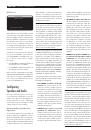
DVD Player
See Figure 6
Standard Definition TVs:
In a system with a standard definition TV,
DVD connections can be made to the VID-
EO 1, 2, 3, 4, or 5 inputs. You may wish to
use VIDEO 4 or VIDEO 5 for DVD players,
since these inputs do not have corresponding
OUTPUT connections. If you choose VIDEO
1, make sure that you use VIDEO 1 inputs
and outputs for all analog audio and video
connections.
Connect a video cable (Composite Video or
S-Video) from the output of the DVD player to
the appropriate VIDEO IN 1–5 input.
NOTE
:
If you plan to distribute video from the
DVD player to a TV monitor in Zone 2, you
must make a Composite Video connection.
High Definition TVs:
If you intend to use the progressive scan
feature with an HDTV monitor, you should
use Component Video and/or HDMI video
connections from the DVD player. If the DVD
player has a DVI-D output, this can usually be
connected to the HDMI input on the RSX-1057
using a DVI-HDMI adapter.
Connect set of Component Video cables or
an HDMI cable from the DVD player to the
appropriate VIDEO 1 or VIDEO 2 input on
the RSX-1057.
Digital Audio connections:
Connect the digital output of the DVD player
to any one of the OPTICAL IN or COAXIAL
IN digital inputs on the RSX-1057. Use the
INPUT SETUP screen to assign that digital
input to the same video input source used
above. For example, if you use the Video 4
inputs above, assign the digital input to the
VIDEO 4 input.
Analog audio connections:
If you want to record the audio signal from
the DVD player or distribute the audio signal
to Zone 2, connect the left and right analog
outputs from the DVD player to the left and
right AUDIO IN jacks corresponding to the
VIDEO IN input selected above.
Cable, Satellite, HDTV Tuner
See Figure 8
Standard Definition TVs:
In a system with a standard definition TV,
cable or satellite tuner connections can be
made to the VIDEO 1, 2, 3, 4, or 5 inputs.
You may wish to use VIDEO 4 or VIDEO 5,
since these inputs do not have corresponding
OUTPUT connections. If you choose VIDEO
1, make sure that you use VIDEO 1 inputs
and outputs for all analog audio and video
connections.
Connect a video cable (Composite Video or
S-Video) from the output of the DVD player to
the appropriate VIDEO IN 1–5 input.
NOTE
:
If you plan to distribute video from the
tuner to a TV monitor in Zone 2, you must
make a Composite Video connection.