www.timberk.com • electrical storage water heater
www.timberk.com • electrical storage water heater
9
8
IMPORTANT!
Please, use accessories, provided by the manu-
facturer, to install the water heater. Electric water
heater must not be mounted on a wall prior you make
sure that the bracket is installed firmly and securely.
Otherwise the electric water heater may fall down
from the wall, which may cause its damage and
even serious accidents involving bodily injury. When
determining points for bolt holes, it is necessary to
provision some spare space between the lower part
of the water heater and the floor, and as to the FSL2/
FSP2 line there also must be some space between
the right side of the water heater and the wall on the
right, not less than 0.6 m to make it convenient to
perform maintenance if necessary.
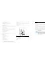
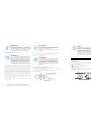
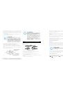
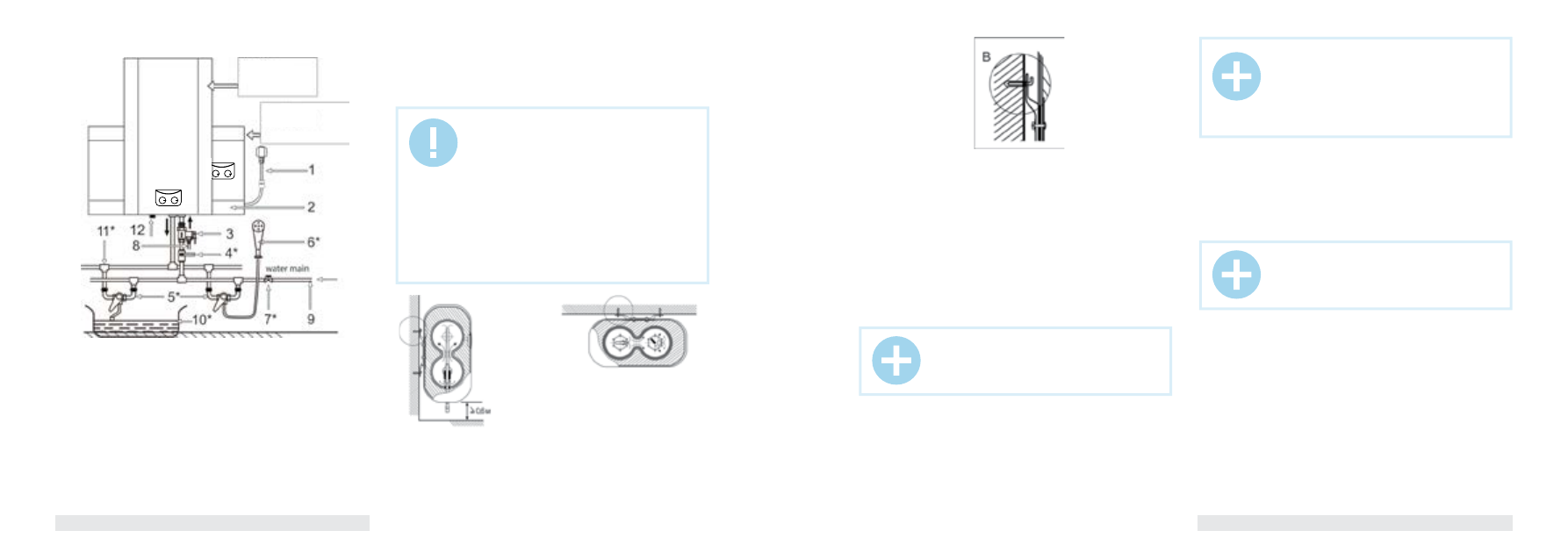
Fig. 7 shows the way to mount the water heater for one consumption point.
1. Power cord with GFCI**
2. Mounted water heater
3. Composite pressure-relief valve
4. Cold water supply valve*
5. Mixer*
6. Shower header*
7. Water main shut-off valve
8. Discharge pipe*
9. Water main
10. Bath*
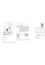
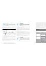
1. Electric water heater should be mounted on a firm wall. If the wall is not
robust enough to hold the weight equal to the doubled weight of the overall
water heater weight, fully filled with water, then it should be mounted on a
special support.
2. G1/2 diameter pipes are used to connect the water heater to the water
pipeline.
3. To prevent a leakage when connecting pipes, use rubber sealing gaskets
on the threaded pipe ends.
4. Screw a relief valve to the inlet nozzle, marked blue and embossed arrow
of the water flow direction, so that the water flow direction coincides with
direction of the arrow on the valve’s case.
5. Water heater with the mounted valve must be connected to the water
main – install a shut-off valve at the water inlet point. You need to connect
a drain pipe to the opening of the pressure relief of safety valve. Next you
should put a drain pipe to the sewer.
6. Connect the desired number of consumption points to the outlet nozzle,
marked red.
7. Check leak integrity of joints: open the shut-off cock and one of the cock
assemblies. After the tank is filled with water, as evidenced by issue of water
from the cock assembly, shut the cock assembly and check the leak integrity
of all joints.
Connection to water main
1. The heater must be connected to water main with at least 0.1 MPa
pressure; maximum pressure is 0.7 MPa.
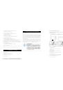
NOTE:
In places or on the wall, where water may get to, the
power outlet installation height must be not less than
1.8 m.
NOTE:
Do not mount additional accessories, such as a shut-
off valve, between the relief valve and the inlet nozzle.
NOTE:
The water heater is the appliance, operating in such
a manner that pressure of water in the water heater
corresponds to the pressure of water in water main.
If pressure in the main exceeds 0.7 MPa, then it is
necessary to mount a pressure reducer before the
water heater so that pressure doesn’t exceed 0.7 MPa.
11. T-joint*
12. Magnesium anode – water discharge nozzle
* not included in the delivery set
** Depending on the product batch, GFCI can be located not within the power cable electric
plug.
Fig. 6
Fig. 7
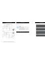
Fig. 8
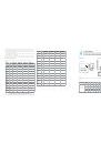
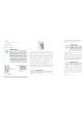
2. After you chose the proper place to install the water heater, determine
points for holes for expansion hook bolts (to be determined in accordance
with the data sheet for the appliance you chose). Drill two holes of the
corresponding depth in the wall using a drill, dimensionally fit for expansion
bolts, enclosed with the water heater, insert bolts, turn the hook upwards,
securely tighten nuts and then hang the electric water heater on these hooks
(see Fig. 8).
3. Fix a power outlet to the wall. Requirements to the outlet are as follows:
230V/10A, single-phase, three-wired. It is recommended to place the outlet
on the right side above the water heater.
4. If a bathroom is too small, the water heater can be installed elsewhere,
unexposed to direct sunlight and unavailable for moisture. However, to
reduce heat losses in pipelines, the location, where a water heater is to be
installed, must be as close to the place, where hot water is used, as possible.
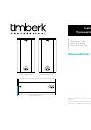
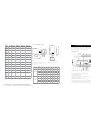
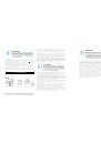
FSL1/FSP1
Vertical position
FSL2/FSP2
Horizontal position
(side view)
for FSL2/FSP2 series
(top view)
for FSL1/FSP1 series