Инструкция для BEST IS ASC 7388

(скачивание инструкции бесплатно)
Формат файла: PDF
Доступность: Бесплатно как и все руководства на сайте. Без регистрации и SMS.
Дополнительно: Чтение инструкции онлайн
background image

ENGLISH

DESCRIPTION

This appliance is equipped with a completely automatic system (Advanced Sensor Control) capable to

manage all the functions of your hood. Thanks to the ASC, the air in the kitchen is costantly clean and odour
free without any manual intervention. The advanced sensor catches all sort of vapours, smokes and odours
caused by the cooking process. The ASC also captures an abnormal presence of GAS.

The unit can be found in filtering hoods, ducting hoods or in hoods with an outside motor.
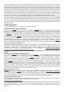
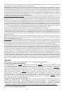
 

In the 

Filtering version

the air and the kitchen fumes that are conveyed by the apparatus are depurated by the charcoal filter and put back into
the room through the small grilles of the ventilation flue (Fig. 1). ATTENTION: When using the filtering version, a charcoal
filter and an air baffle (Fig. 1A) must be used, which placed at the top of the structure, allows the air to recycle back into
the room.


In the 

Ducting version

, cooking vapours and odours are conveyed straight outside by a disposal duct which

passes through the ceiling (Fig. 2).


In the hoods with an 

outside motor

 (Fig. 3), a vacuum suction unit must be connected;

this exhaust will operate separately, conveying the exhaust air through the unit. 

Only use vacuum units suggested in

the original catalogue.

INSTALLATION

ATTENTION: Two persons are required for proper installation; the unit should be installed by a qualified operator.

Also follow carefully each step of the assembly instructions, and once installation has been completed, make sure
that the hood is firmly secured in place.

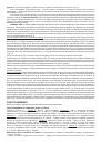
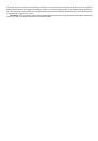
To facilitate installation, before starting remove the 

grease filters

: press inward on the clamp at the handle and pull

the filter downward (Fig. 4).

For assembling it is essential to: – Prepare the connection to the mains within the telescopic flue. – If your unit is

installed in an ducting hood or in a hood with outside motor, prepare the air exhaust hole.

When installing ducting hoods and hoods with outside motor, to achieve the best possible conditions use an 

air exhaust

pipe

 that : is as short as possible, has a minimum of curves (maximum angle: 90°), is made of a material that complies

with the standards (which vary from nation to nation) and iv) is smooth on the inside.  It is also advisable to avoid any
drastic changes in pipe section (diameter: 150 mm).
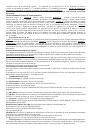
ASSEMBLING - 

Using the special drilling template, drill the holes for fixing to the ceiling on the vertical side of your

hob. Carefully observe all the indications for final positioning of the apparatus. Take into account that one of the template
axes must correspond to the axis of the hood controls. Fix the bracket to the ceiling using the screws and screw anchors
provided (Fig. 5). Be careful, because the position of the bracket determines the final position of the apparatus: the side
with the slot B corresponds to the side opposite the commands. Mount the plate of the electrical system fixing it with 3
screws and 2 metal washers (Fig. 6).
Ducting version and version with an external motor: Fix the telescopic structure to the bracket by means of 4 screws
(provided), running the air evacuation pipe through the telescopic structure and the electric power cable through the special
hole in the bracket (Fig. 7). Adjust the height of the telescopic structure by means of the four retaining screws C (Fig.8),
taking into account that the height of the hood is 86 mm and that the distance between the hood and the hob must be
at least 650 mm (Fig. 9).  Take the upper pipe (with the round slots) and fit it on the telescopic structure with the slots
facing downwards; fit the pipe to the bracket with 2 screws (Fig. 10). Take the lower pipe and fit it in the same manner
as before; slide it to the top and stop it in that position using a screw inserted in the hole of the upper pipe as a catch
(Fig. 11). Fit the hood to the telescopic structure by means of 4 screws (provided) – Fig. 12.     Through the openings
D (Fig. 12) fix the air evacuation pipe to the air outlet mouth of the hood.
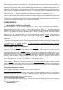
Only for models with outside motor (Fig. 13): plug the hood into the outside control unit using the special terminal block:
remove wire clamp A and lid B from the wiring junction box; secure the wire connecting the control unit to terminal C; then
replace wire clamp A and lid B on the wiring junction box; the other end of the wire is secured to the terminal block on
the outside control unit.
Make the electrical connection by means of the power  cable. Remove the screw used as catch and slide the lower pipe
downwards, placing it gently on the apparatus.  Installation is now complete and the anti-grease filters can be remounted.
Filtering version: Fix the telescopic structure to the bracket by means of 4 screws (provided), running the electric power
cable through the special hole in the bracket (Fig. 7). Adjust the height of the telescopic structure by means of the four
retaining screws C (Fig. 8), taking into account that the height of the hood is 86 mm and that the distance between the
hood and the hob must be at least 650 mm (Fig. 9). Insert the air baffle in the structure (Fig.14). Through the openings
E (Fig.14), fit the flange to the baffle locking it with a turning movement.  Fix a flexible pipe to the flange for air evacuation
(Fig. 15). Take the upper pipe (with the round slots) and fit it on the telescopic structure with the slots facing upwards;
fit the pipe to the bracket with 2 screws (Fig. 16). Take the lower pipe and fit it in the same manner as before; slide it to
the top and stop it in that position using a screw inserted in the hole of the upper pipe as a catch (Fig. 11). Fit the hood
to the telescopic structure by means of 4 screws (provided) – Fig. 17.     Through the openings D, mount the flange (provided)
on the air outlet mouth of the hood (Fig. 17). Then fit the air evacuation pipe to the flange. Make the electrical connection
by means of the power cable. Remove the screw used as catch and slide the lower pipe downwards, placing it gently on
the apparatus. Install the charcoal filter clipping the 2 filter clips into place (Fig. 18) and turn the filter upwards. Installation
is now complete and the anti-grease filters can be remounted.

1
2
3
4
5
6
7
8
9
10
11
12
13
14
15
16
17
18
19
20
21
22
23
24
Оглавление инструкции
  • Страница 1 из 25
    INSTRUCTIONS FOR INSTALLATION AND USE MONTAGE- UND GEBRAUCHSANWEISUNG INSTRUCTIONS POUR L'INSTALLATION ET L’UTILISATION ISTRUZIONI PER L'INSTALLAZIONE E L’USO INSTRUCCIONES PARA INSTALACIÓN Y USO INSTRUÇÕES DE INSTALAÇÃO Y UTILIZAÇÃO AANWIJZING VOOR GEBRUIK EN INSTALLATIE
  • Страница 2 из 25
  • Страница 3 из 25
    ENGLISH DESCRIPTION This appliance is equipped with a completely automatic system (Advanced Sensor Control) capable to manage all the functions of your hood. Thanks to the ASC, the air in the kitchen is costantly clean and odour free without any manual intervention. The advanced sensor catches all
  • Страница 4 из 25
    OPERATION Depending on the model, the unit is equipped with the following commands: AUTOMATIC OPERATION WITH SENSOR: See Figure 19. Key A : switches the lights on/off. Key B : enables/disables “Automatic” function. When this function is selected, an “A” appears on the display C, and the speed of
  • Страница 5 из 25
    Grease filters: special attention must be given to the grease filters which must be periodically cleaned, whenever the grease filter alarm trips. For instructions of the filter Alarm, refer to the Controls paragraph. Remove the filters as shown in para. 1 and wash with neutral detergent. Charcoal
  • Страница 6 из 25
    Stromversorgungskabel durch die entsprechende Öffnung am Bügel verlaufen sollen (Abb. 7). Die Höhe der Teleskopkonstruktion mit den vier Befestigungsschrauben C (Abb. 8) einstellen und dabei berücksichtigen, dass die Höhe der Haube 86 mm beträgt und dass der Abstand der Haube vom Kochfeld zumindest
  • Страница 7 из 25
    Durch die nochmalige Betätigung der Taste B erfolgt die Einstellung auf den manuellen Betrieb. Betriebsweise als herkömmliche Abzugshaube: Bei automatischer Betriebsart auf die Taste B drücken. Somit erfolgt der Übergang auf die manuelle Betriebsart und die LED B erlischt. Durch Betätigung einer
  • Страница 8 из 25
    graisse: à l'aide de la poignée, pousser l’arrêt vers l’intérieur et tirer le filtre vers le bas (Fig. 4). Pour l’assemblage, il est essentiel que: – vous ayez prévu l’alimentation électrique à l’intérieur de la structure télescopique. – Si l'appareil doit être installé en version Aspirante ou en
  • Страница 9 из 25
    visualise l’indice de sensibilité du capteur). - En appuyant sur les touches D ou E, on augmente ou diminue l’indice de sensibilité du capteur (1 : sensibilité minimum / 9: sensibilité maximum). - en cas de coupure de l’alimentation électrique, le capteur fonctionne de nouveau avec sensibilité 5.
  • Страница 10 из 25
    Filtres à charbon: Si l’on utilise l’appareil en version filtrante, il faut remplacer périodiquement les filtres à charbon, quand intervient l’alarme des filtres à charbon. Pour les instructions, concernant l’alarme des filtres, voir le paragraphe des Commandes. Démontage du filtre(s) à charbon:
  • Страница 11 из 25
    elettrica attraverso l'apposito foro della staffa (Fig. 7). Regolate l'altezza della struttura telescopica tramite le quattro viti di fissaggio C (Fig. 8) tenendo conto che l'altezza della cappa è di 86 mm e che la distanza della cappa dal piano cottura deve essere minimo 650 mm. (Fig. 9). Infilare
  • Страница 12 из 25
    P2) ON Luci: Se premuto si accendono le luci. P3) OFF/- Motore: Decrementa la velocità fino ad arrivare alla minima velocità. Se premuto per 2" viene spento il motore. Se premuto per 2" quando è attivo il RESET FILTRI azzera il conteggio ORE. P4) ON/+ Motore: Accende il motore e incrementa la
  • Страница 13 из 25
    MONTAJE - Mediante el uso de una adecuada máscara de agujerear realizar los agujeros para fijar al techo sobre la vertical respecto a Vuestro plano de cocción; tener cuidado a todas las indicaciones para la ubicación final del aparato. Se debe tener en cuenta que uno de los ejes de la máscara debe
  • Страница 14 из 25
    botón durante la visualización de la alarma filtros, se activa el RESET y, por consiguiente, el cálculo de las horas se repone en marcha. Botón E : acciona el motor / aumenta la velocidad del motor / TEMPORIZADOR. Pulsando el botón, se acciona el motor (a la última velocidad seleccionada);
  • Страница 15 из 25
    PORTOGUÊS DESCRIÇÃO Este exaustor está equipado de um sistema completamente automático (Advanced Sensor Control), que controla todas as suas funções. Graças ao Advanced Sensor Control, o ar na cozinha mantém-se sempre limpo e sem cheiros e isto sem alguma intervenção do utilizador. Os sofisticados
  • Страница 16 из 25
    introduzindo um parafuso no orifício do tubo superior, a servir de trava (Fig. 11). Fixar a capa na estrutura telescópica mediante 4 parafusos (presentes na embalagem) - Fig. 17. Através das aberturas D, montar a redução (presente na embalagem) na boca de saída de ar da capa (Fig. 17); fixar então
  • Страница 17 из 25
    P4) ON/+ Motor: Liga o motor e aumenta a velocidade do motor até à velocidade máxima P5) ON/OFF: Activa/desactiva o Sensor( modo de funcionamento AUTOMÁTICO ou MANUAL). No modo de funcionamento Automático o Led L2 está aceso e o led L1 indica a velocidade que está em execução. No modo de
  • Страница 18 из 25
    (afhankelijk van het land), zo glad mogelijke binnenzijde. Er wordt bovendien geadviseerd om drastische veranderingen van de doorsnede van de pijp (diameter: 150 mm) te vermijden. MONTAGE - Maak gebruik van de speciale boormal en boor de gaten voor de bevestiging aan het plafond exact op de
  • Страница 19 из 25
    WERKING ALS EEN TRADITIONELE AFZUIGKAP : Verwijzing Afbeelding 19. Toets A : schakelt de verlichting in/ uit. Display C : - duidt de gekozen snelheid van de motor aan (van 1 tot 4); - duidt de inwerkingstelling van de Timer aan wanneer het getal knippert; duidt het filteralarm aan wanneer het
  • Страница 20 из 25
    vervangen, wanneer het alarm “koolstoffilters” verschijnt. Voor instructies over het alarm van de filters, zie de paragraaf Bedieningselementen. Demontage koolstoffilter(s): neem ten eerste de vetfilters weg. Duw de vergrendeling naar binnen (afb. 18) en verwijder de koolstoffilter van zijn plaats.
  • Страница 21 из 25
    1 2 3 A 4 6 5 7 8 B C
  • Страница 22 из 25
    9 10 11 86 min 65cm E 14 12 D 13 15 A B C
  • Страница 23 из 25
    17 16 D 18 19 20 A S A 21 B C D E 22 B C D R
  • Страница 24 из 25
    04307092 - ISASC7388/7387s.n.
  • Страница 25 из 25