ENGLISH
DESCRIPTION
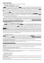
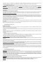
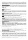
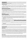
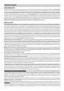
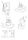
The unit can be found in filtering hoods, exhaust hoods or in hoods with an outside motor. In the Filtering hoods (Fig.1)
the air and steam taken up by the unit are purified with charcoal filters and returned to the environment through the aeration
grids on the side of the flue. WARNING: When using filtering hoods, both charcoal filters and an air deflector must be
used. Located in the upper part of the flue, this deflector recycles the air to the environment (Fig. 1A). In the Exhaust
hoods (Fig.2) an exhaust duct conveys the steam and cooking odors directly outside through the wall/ceiling. Therefore
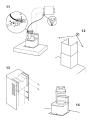
they do not require charcoal filters. In the hoods with an outside motor (Fig. 3), a vacuum suction unit must be connected;
this exhaust will operate separately, conveying the exhaust air through the unit. Only use vacuum units suggested in
the original catalogue.
INSTALLATION
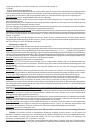
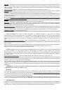
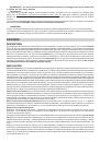
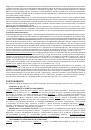
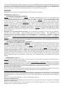
Installation on the wall (Fig. 4): Using the special drilling template, drill the required holes in the wall. As previously specified
in the chapter “Warning” remember there must be a minimum of 650 mm between the bottom edge of the hood and the
stop of the stove. Secure the metal bracket (B) to the wall using the screws and plugs (bracket, screws and plugs are
all supplied with the unit). Use the 2 triangles cut into the bracket to position it precisely along the vertical axis of the
hood. Then set the hood onto the bracket. Adjust the horizontal position, shifting the hood to the right or left as needed
lining it up with the wall units. If the height of the hood also requires adjustment, use the special regulation screws (V)
(supplied). Once regulation has been completed, finish securing the hood with 4 more screws M (or 6 screws M+M1,
depending on the model): mark the points for the 4 holes (or 6) on the wall, remove the hood and drill (8mm diameter holes);
then use the plugs and screws to complete installation.
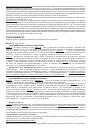
Installation with rear panel (Fig. 5): The rear panel is positioned at the top of the stove, flush against the wall. Rest
the lower edge of the panel behind the stove and anchor the upper edge to the wall using the two holes found on the panel.
Insert the screws and plugs provided (A). The unit is secured to the rear panel as though it were being installed on the
wall: use the supplied metal bracket (B) and the screws and plugs supplied with the panel.
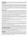
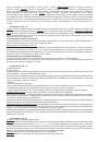
Fit the electric system plate securing it with 2 screws (or 3 screws depending on the version) - Fig. 6 / 7. For some models
2 notched washers must also be used (check if the washers are contained in the accessory bag provided with your hood;
if yes, use them to fit the electric system plate).
Securing the extension flues:
Basic installation requirements: – Set the electrical power supply within the space covered by the decorative flues.
– If your unit is installed in an Exhaust hood or in a hood with outside motor, prepare the air exhaust hole.
When installing exhaust hoods and hoods with outside motor, to achieve the best possible conditions use an air exhaust
pipe that : is as short as possible, has a minimum of curves (maximum angle: 90°), is made of a material that complies
with the standards (which vary from nation to nation) and iv) is smooth on the inside. It is also advisable to avoid any
drastic changes in pipe section (diameter: 150 mm).
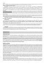
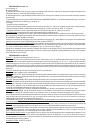
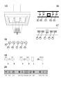
Adjust the width of the extension flue support bracket (W) using screws A indicated in Fig. 8. Then use the plugs and
screws provided to secure it to the ceiling. Make certain it is aligned with the hood. For filtering hoods, the air exhaust
grids are positioned in the upper part (Fig. 9). For exhaust hoods, turn the upper flue over so that the air exhaust grid
is in the lower section (Fig. 10).
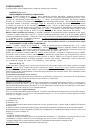
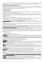
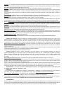
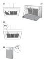
Exhaust hoods and hoods with outside motors: Connect the hood flange to the exhaust hole in the wall/ceiling using a
flexible pipe. Only for models with outside motor (Fig. 11): plug the hood into the outside control unit using the special
terminal block: remove wire clamp A and lid B from the wiring junction box. Secure the wire connecting the control unit
to terminal C. Then replace wire clamp A and lid B on the wiring junction box. The other end of the wire is secured to the
terminal block on the outside control unit. Plug in the hood. Insert the extension flues setting them on the hood; extend
the upper flue to the ceiling and secure with the 2 screws (G) - Fig. 12.
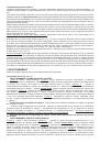
Filtering hood: Secure the deflector to the upper flue using the 4 special screws (provided) – Fig. 13; hook up the flexible
pipe (diameter: 125) to the deflector. Install the reduction (provided) on the hood air outlet point (Fig. 14). Take the 2
assembled extension flues and set them on the hood; extend the upper flue to the ceiling and secure with the 2 screws
(G) - Fig. 12. Extend the lower flue taping it in place and then connect the flexible pipe to the hood reduction. Plug in
the hood. Extend the lower flue downward setting it against the hood. Install the charcoal filter by pressing the 2 tabs
on the filter down into the special housing (Fig. 15) and rotating upward.
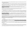
OPERATION
Depending on the model, the unit is equipped with the following controls:
Controls in Fig. 16 / 17:
AUTOMATIC OPERATION WITH SENSOR:
Key A : switches the lights on/off. Key B : enables/disables “Automatic” function. When this function is selected,
an “A” appears on the display C, and the speed of the motor increases or decreases depending on the smoke,
odours and gas present in the kitchen. Display C : - indicates the automatic operation of the sensor (the
letter “A” appears);- indicates the motor speed selected automatically by the sensor; indicates the filter alarm
whenever the central segment is illuminated or flashing. Key D : decreases motor speed / Reset; decreases