Hardware Installation
- 24 -
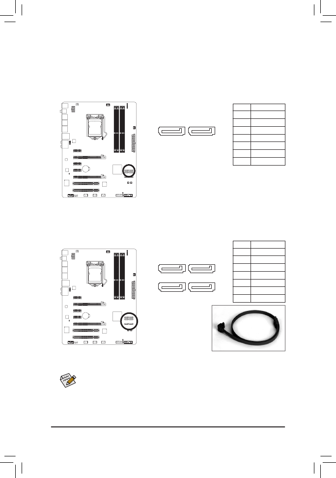
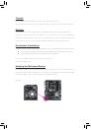
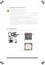
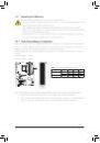
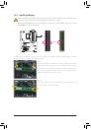
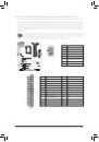
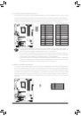
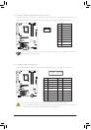
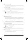
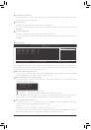
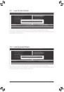
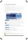
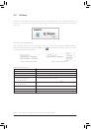
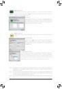
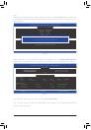
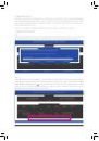
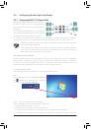
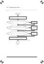
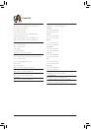
8) SATA2_2/3/4/5 (SATA 3Gb/s Connectors, Controlled by P67 Chipset)
The SATA connectors conform to SATA 3Gb/s standard and are compatible with SATA 1.5Gb/s stan-
dard. Each SATA connector supports a single SATA device. The P67 controller supports RAID 0,
RAID 1, RAID 5, and RAID 10. Refer to Chapter 5, "Configuring SATA Hard Drive(s)," for instructions on
configuring a RAID array.
Pin No. Definition
1
GND
2
TXP
3
TXN
4
GND
5
RXN
6
RXP
7
GND
• A RAID 0 or RAID 1 configuration requires at least two hard drives. If more than two hard
drives are to be used, the total number of hard drives must be an even number.
• A RAID 5 configuration requires at least three hard drives. (The total number of hard drives
does not have to be an even number.)
• A RAID 10 configuration requires four hard drives.
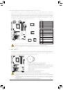
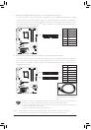
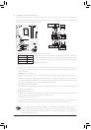
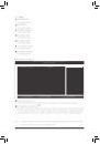
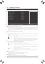
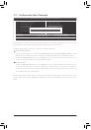
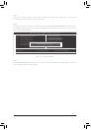
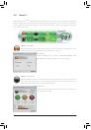
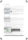
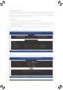
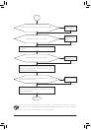
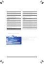
7) SATA3_0/1 (SATA 6Gb/s Connectors, Controlled by P67 Chipset)
The SATA connectors conform to SATA 6Gb/s standard and are compatible with SATA 3Gb/s and SATA
1.5Gb/s standard. Each SATA connector supports a single SATA device. The SATA3_0 and SATA3_1
connectors support RAID 0 and RAID 1. RAID 5 and RAID 10 can be implemented on the two connec-
tors with the SATA2_2/3/4/5 connector
(Note)
. Refer to Chapter 5, "Configuring SATA Hard Drive(s)," for
instructions on configuring a RAID array.
Pin No. Definition
1
GND
2
TXP
3
TXN
4
GND
5
RXN
6
RXP
7
GND
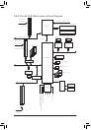
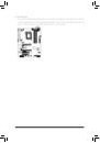
SATA3_0
SATA3_1
1
7
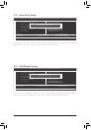
DEBUG
PORT
DEBUG
PORT
SATA2_4
SATA2_2
SATA2_3
SATA2_5
1
7
DEBUG
PORT
DEBUG
PORT
DEBUG
PORT
DEBUG
PORT
(Note) When a RAID set is built across the SATA 6Gb/s and SATA 3Gb/s channels, the system
performance of the RAID set may vary depending on the devices being connected.
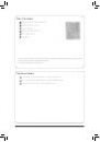
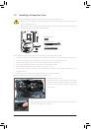
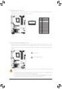
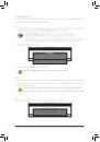
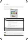
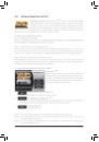
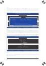
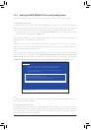
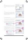
Please connect the L-shaped end of
the SATA cable to your SATA hard
drive.
 1
1
 2
2
 3
3
 4
4
 5
5
 6
6
 7
7
 8
8
 9
9
 10
10
 11
11
 12
12
 13
13
 14
14
 15
15
 16
16
 17
17
 18
18
 19
19
 20
20
 21
21
 22
22
 23
23
 24
24
 25
25
 26
26
 27
27
 28
28
 29
29
 30
30
 31
31
 32
32
 33
33
 34
34
 35
35
 36
36
 37
37
 38
38
 39
39
 40
40
 41
41
 42
42
 43
43
 44
44
 45
45
 46
46
 47
47
 48
48
 49
49
 50
50
 51
51
 52
52
 53
53
 54
54
 55
55
 56
56
 57
57
 58
58
 59
59
 60
60
 61
61
 62
62
 63
63
 64
64
 65
65
 66
66
 67
67
 68
68
 69
69
 70
70
 71
71
 72
72
 73
73
 74
74
 75
75
 76
76
 77
77
 78
78
 79
79
 80
80
 81
81
 82
82
 83
83
 84
84
 85
85
 86
86
 87
87
 88
88
 89
89
 90
90
 91
91
 92
92
 93
93
 94
94
 95
95
 96
96
 97
97
 98
98
 99
99
 100
100
 101
101
 102
102
 103
103
 104
104