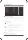
- 25 -
Hardware Installation
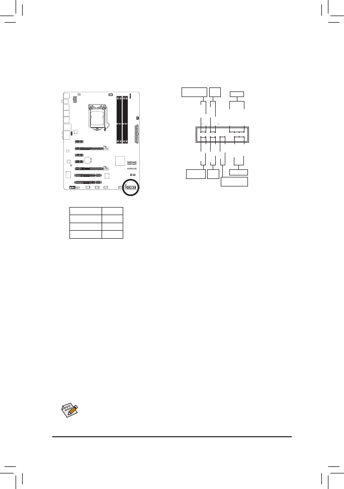
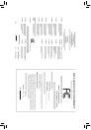
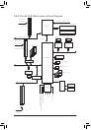
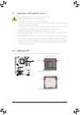
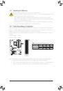
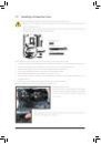
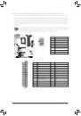
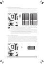
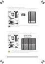
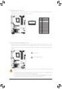
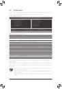
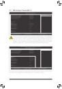
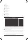
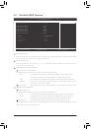
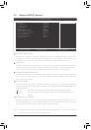
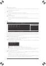
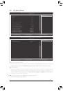
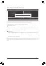
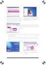
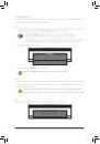
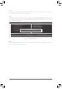
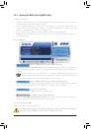
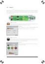
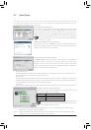
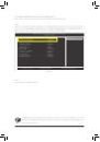
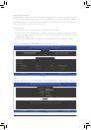
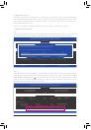
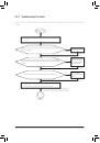
9) F_PANEL (Front Panel Header)
Connect the power switch, reset switch, speaker, chassis intrusion switch/sensor and system status
indicator on the chassis to this header according to the pin assignments below. Note the positive and
negative pins before connecting the cables.
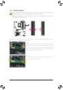
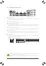
• PW (Power Switch, Red):
Connects to the power switch on the chassis front panel. You may configure the way to turn off your
system using the power switch (refer to Chapter 2, "BIOS Setup," "Power Management Setup," for
more information).
• SPEAK (Speaker, Orange):
Connects to the speaker on the chassis front panel. The system reports system startup status by is-
suing a beep code. One single short beep will be heard if no problem is detected at system startup. If
a problem is detected, the BIOS may issue beeps in different patterns to indicate the problem. Refer
to Chapter 5, "Troubleshooting," for information about beep codes.
• HD (Hard Drive Activity LED, Blue)
Connects to the hard drive activity LED on the chassis front panel. The LED is on when the hard drive
is reading or writing data.
• RES (Reset Switch, Green):
Connects to the reset switch on the chassis front panel. Press the reset switch to restart the computer
if the computer freezes and fails to perform a normal restart.
• CI (Chassis Intrusion Header, Gray):
Connects to the chassis intrusion switch/sensor on the chassis that can detect if the chassis cover
has been removed. This function requires a chassis with a chassis intrusion switch/sensor.
• MSG/PWR (Message/Power/Sleep LED, Yellow/Purple):
Connects to the power status indicator on the chassis front panel. The LED
is on when the system is operating. The LED keeps blinking when the sys-
tem is in S1 sleep state. The LED is off when the system is in S3/S4 sleep
state or powered off (S5).
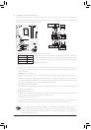
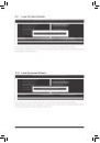
System Status LED
S0
On
S1
Blinking
S3/S4/S5
Off
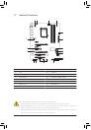
The front panel design may differ by chassis. A front panel module mainly consists of power
switch, reset switch, power LED, hard drive activity LED, speaker and etc. When connecting your
chassis front panel module to this header, make sure the wire assignments and the pin assign-
ments are matched correctly.
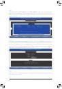
Power LED
DEBUG
PORT
1
2
19
20
CI-
CI+
PWR-
PWR+
MSG-
PW
-
SPEAK+
SPEAK-
MSG+
PW+
Message/Power/
Sleep LED
Speaker
Power
Switch
HD-
RES+
HD+
RES-
Hard Drive
Activity LED
Reset
Switch
Chassis Intrusion
Header
 1
1
 2
2
 3
3
 4
4
 5
5
 6
6
 7
7
 8
8
 9
9
 10
10
 11
11
 12
12
 13
13
 14
14
 15
15
 16
16
 17
17
 18
18
 19
19
 20
20
 21
21
 22
22
 23
23
 24
24
 25
25
 26
26
 27
27
 28
28
 29
29
 30
30
 31
31
 32
32
 33
33
 34
34
 35
35
 36
36
 37
37
 38
38
 39
39
 40
40
 41
41
 42
42
 43
43
 44
44
 45
45
 46
46
 47
47
 48
48
 49
49
 50
50
 51
51
 52
52
 53
53
 54
54
 55
55
 56
56
 57
57
 58
58
 59
59
 60
60
 61
61
 62
62
 63
63
 64
64
 65
65
 66
66
 67
67
 68
68
 69
69
 70
70
 71
71
 72
72
 73
73
 74
74
 75
75
 76
76
 77
77
 78
78
 79
79
 80
80
 81
81
 82
82
 83
83
 84
84
 85
85
 86
86
 87
87
 88
88
 89
89
 90
90
 91
91
 92
92
 93
93
 94
94
 95
95
 96
96
 97
97
 98
98
 99
99
 100
100
 101
101
 102
102
 103
103
 104
104