- 27 -
Hardware Installation
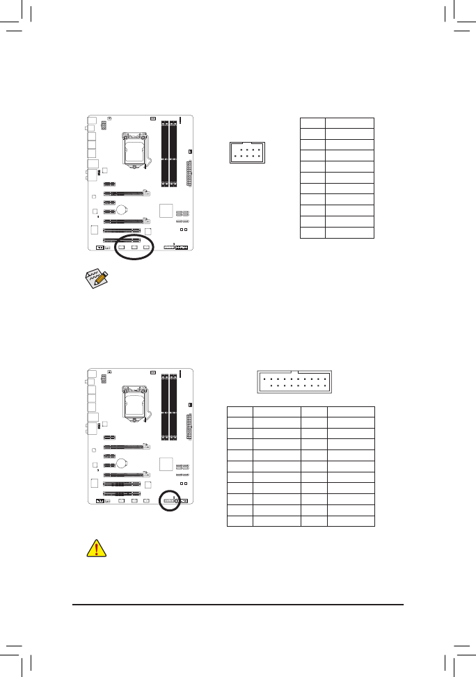
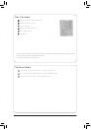
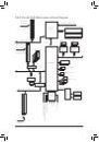
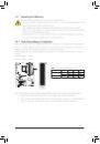
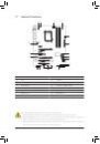
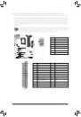
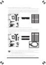
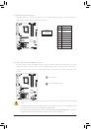
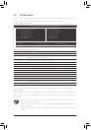
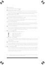
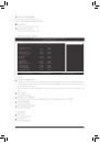
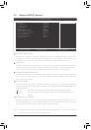
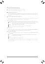
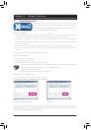
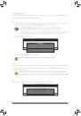
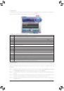
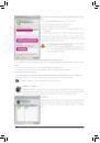
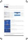
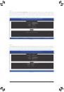
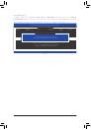
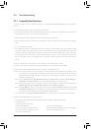
12) F_USB1/F_USB2/F_USB3 (USB 2.0/1.1 Headers)
The headers conform to USB 2.0/1.1 specification. Each USB header can provide two USB ports via an
optional USB bracket. For purchasing the optional USB bracket, please contact the local dealer.
DEBUG
PORT
10
9
2
1
Pin No. Definition
1
Power (5V)
2
Power (5V)
3
USB DX-
4
USB DY-
5
USB DX+
6
USB DY+
7
GND
8
GND
9
No Pin
10
NC
When the system is in S4/S5 mode, only the USB ports routed to the F_USB1 header can sup-
port the ON/OFF Charge function.
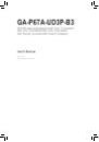
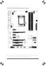
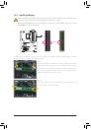
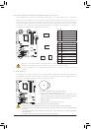
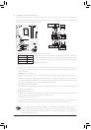
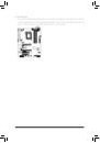
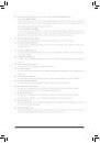
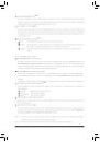
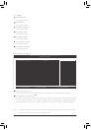
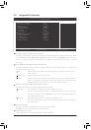
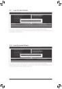
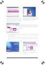
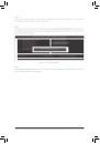
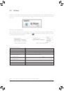
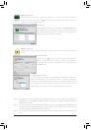
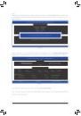
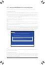
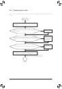
13) F_USB30 (USB 3.0/2.0 Header)
The header conforms to USB 3.0/2.0 specification. Each USB header can provide two USB ports.
F_USB30
F_AUDIO(H)
DB_PORT
F_PANEL(NH)
F_PANEL
(H61M-D2)
TPM
w/housing
10
11
20
1
Pin No. Definition
11
D2+
12
D2-
13
GND
14
SSTX2+
15
SSTX2-
16
GND
17
SSRX2+
18
SSRX2-
19
VBUS
20
No Pin
Pin No. Definition
1
VBUS
2
SSRX1-
3
SSRX1+
4
GND
5
SSTX1-
6
SSTX1+
7
GND
8
D1-
9
D1+
10
NC
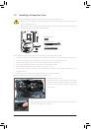
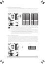
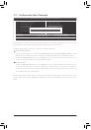
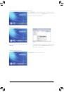
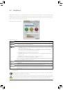
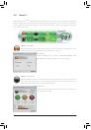
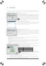
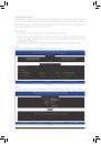
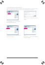
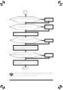
• Do not plug the IEEE 1394 bracket (2x5-pin) cable into the USB 2.0/1.1 header.
• Prior to installing the USB bracket, be sure to turn off your computer and unplug the power
cord from the power outlet to prevent damage to the USB bracket.
 1
1
 2
2
 3
3
 4
4
 5
5
 6
6
 7
7
 8
8
 9
9
 10
10
 11
11
 12
12
 13
13
 14
14
 15
15
 16
16
 17
17
 18
18
 19
19
 20
20
 21
21
 22
22
 23
23
 24
24
 25
25
 26
26
 27
27
 28
28
 29
29
 30
30
 31
31
 32
32
 33
33
 34
34
 35
35
 36
36
 37
37
 38
38
 39
39
 40
40
 41
41
 42
42
 43
43
 44
44
 45
45
 46
46
 47
47
 48
48
 49
49
 50
50
 51
51
 52
52
 53
53
 54
54
 55
55
 56
56
 57
57
 58
58
 59
59
 60
60
 61
61
 62
62
 63
63
 64
64
 65
65
 66
66
 67
67
 68
68
 69
69
 70
70
 71
71
 72
72
 73
73
 74
74
 75
75
 76
76
 77
77
 78
78
 79
79
 80
80
 81
81
 82
82
 83
83
 84
84
 85
85
 86
86
 87
87
 88
88
 89
89
 90
90
 91
91
 92
92
 93
93
 94
94
 95
95
 96
96
 97
97
 98
98
 99
99
 100
100
 101
101
 102
102
 103
103
 104
104