Warnings:
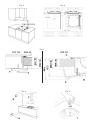
This appliance is designed to be built into a housing unit.
-
The installation class is type 3 for gas and type Y for electric parts.
-
Housing units must be designed to withstand temperatures of up to 90°C or over.
-
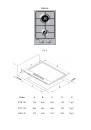
For correct installation, refer to the relevant paragraph and reference drawings.
-
The use of a gas cooking appliance produces heat and humidity in the room in which it is
installed. Ensure the kitchen is well ventilated: keep natural ventilation openings open, or install
a mechanical ventilation device (extractor hood with exhaust duct). In the case of intensive or
prolonged use of the appliance it may be necessary to provide additional ventilation, for example,
by opening a window, or more efficient ventilation, for example by increasing the hood speed.
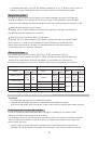
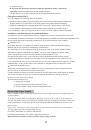
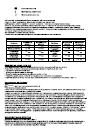
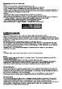
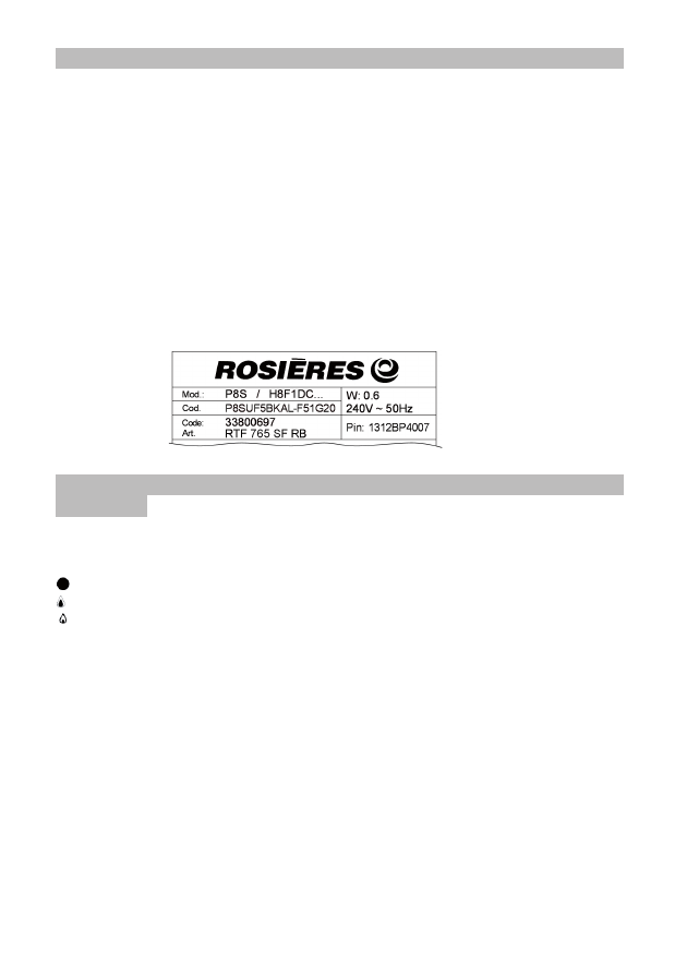
This handbook is valid for several types of cooktop.
Refer to the data plate on the back in order to identify the model that corresponds to your appliance.
These informations, together with the instructions and the illustrations in the following paragraphs
will show you the characteristics of your appliance.
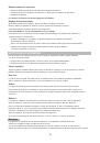
An Example:
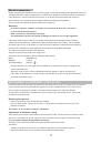
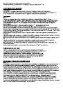
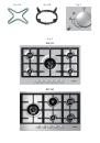
Gas burners
The delivery of gas to the burners is controlled by the knobs shown in fig.2 that in turn control the taps.
The symbols, depending on the various versions, may be printed over or under the knobs.
By moving the indicator to coincide with the printed symbols, the following adjustment can be made:
Tap closed, no gas delivery
Maximum capacity, maximum gas delivery
Minimum capacity, minimum gas delivery
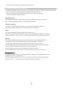
Burners ignition
These models are equipped with safety valves which automatically shut off the gas delivery
in the event the burner should, for any reason, go out. To relight the burner, turn the knob to
position "tap closed" and repeat the ignition procedure explained in the following paragraphs.
For ignite a burner, turn the gas tap knob to the maximum
delivery position, then press and hold down it for about 4÷5 seconds.
Warnings:
-
Once the burner is light on, adjust the flame by turning the knob to obtain the desired intensity.
The setting must always be positioned between the maximum and minimum, and never
between the maximum setting and the off position.
-
If the burner is difficult to light on, or if the flame is tall or irregolar, turn off immediately
turning the knob to "off" position and call Assistance Service.
-
If the particular nature of the local gas supply makes it difficult to ignite the burners with the knob
turned to the maximum setting, repeat the operation without a pan in position and with the knob
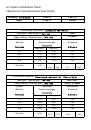
USING THE COOKTOP
COOKTOP SPECIFICATIONS
8