Инструкция для Rosieres RTE 753 SF IN, RTF 765 SF IN

(скачивание инструкции бесплатно)
Формат файла: PDF
Доступность: Бесплатно как и все руководства на сайте. Без регистрации и SMS.
Дополнительно: Чтение инструкции онлайн
background image

 -

leaving the burner alight for a few minutes, it doesn't go over

To maintain the cooktop in optimum condition, clean it regularly after each use, allowing it to cool before cleaning

 -

Never use abrasive or sharp substances or materials to clean the surfaces

 -

Never clean the appliance with high pressure water or steam cleaning equipment

 -

Do not use flamable or alcoolic cleaners

Enamelled parts:

All enamelled parts should be cleaned with a sponge and soapy water or specific detergents.

Never use abrasive cleaning products. Dry thoroughly after cleaning.

Stainless steel top:

The stainless steel top should be cleaned with a damp cloth and proprietary detergents

commercially available. After rinsing, dry preferably with a chamois leather.
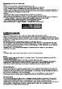
Grids:

The enamelled panstand grids of the cooktop are dishwasher safe.

Stainless steel panstand grids may take on a bluish tinge on parts around the burners as a result of

the high temperatures. This effect can be reduced by using commercially available steel wool pads.

Burners:

The burners, comprising two parts, can be removed and cleaned using suitable detergents.

After cleaning, dry the burners thoroughly and reposition them carefully in their seats.

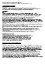
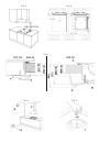
In models with electric ignition, always check that the electrode “E” (fig.11) is clean.

In models with safety device, clean the probe “T” (fig.11) in order to allow regular operation of the

safety valve. Both the electrode and probe must be cleaned with care.

Upon completion of cleaning, replace the burners accurately in their seats.

To prevent damaging the electric ignition, avoid using it when the burners are not in place.

Maintenance

The appliances do not require any particular maintenance, nonetheless it is advisable to have them

checked at least once every two years.

If the knobs become difficult to turn, or if there is a smell of gas, shut the gas supply tap and call

After-sales service.

Faulty taps must be replaced along with their gasket.

CLEANING AND MAINTENANCE

12

1
2
3
4
5
6
7
8
9
10
11
12
13
14
15
16
17
18
19
20
21
22
23
24
25
26
27
28
Оглавление инструкции
  • Страница 1 из 29
    NOTICE D'INSTRUCTIONS plans de cuisson à encastrer INSTRUCTIONS BOOKLET built-in cooktops
  • Страница 2 из 29
  • Страница 3 из 29
    Avertissements et conseils importants pour l'utilisation IMPORTANT ! Ce manuel fait partie intégrante de l'appareil. Il faut le conserver en bon état et à portée de la main pour tout le cycle de vie de la table de cuisson. Lire attentivement ce manuel et toutes les indications qu'il contient avant
  • Страница 4 из 29
    CARACTERISTIQUES DU PLAN Avertissements: Cet appareil est prévu pour être encastré dans des meubles. - La classe d'installation est du type 3 pour la partie à gaz et du type Y pour la partie électrique. Les meubles doivent résister à une température d'au moins 90°C. Pour effectuer une installation
  • Страница 5 из 29
    - Le dispositif d'allumage ne peut pas être actionné pendant plus de 15”. Si, après ce laps de temps, le brûleur ne s'est pas encore allumé, attendre une minute avant de recommencer l’opération. Emploi des grilles Les grilles du plan de cuisson ont été conçues pour faciliter l’utilisation du
  • Страница 6 из 29
    - En cas d'accouplement plan/four, intercaler un séparateur à une distance minimale de 15 mm suivre les indications du fournisseur du four en maintenant toujours une aération fidèle aux instructions de fig.6. De toute manière, le branchement électrique des deux appareils doit être réalisé
  • Страница 7 из 29
    Le raccordement au gaz doit être exécuté par un technicien spécialisé qui respectera les normes locales en vigueur. Le plan de cuisson doit être raccordé à l'installation du gaz en utilisant des tuyaux métalliques rigides ou des tuyau x flexibles en acier inox le long du mur, conformes à la norme
  • Страница 8 из 29
    Remplacement des injecteurs: - Retirer les grilles du plan de cuisson ainsi que le chapeau du brûleur À l'aide d'une clé fixe, remplacer les injecteurs "J" (fig.9) par ceux adaptés au gaz utilisé. Remonter les brûleurs Les brûleurs n'ont besoin d'aucun réglage de l'air primaire Réglage du minimum
  • Страница 9 из 29
    Important warnings and tips for use IMPORTANT! This manual constitutes an integral part of the appliance. It must be kept intact and within easy reach during the entire life of the cooktop. Please carefully read this manual and all the instructions contained herein before using the appliance. Keep
  • Страница 10 из 29
    COOKTOP SPECIFICATIONS Warnings: This appliance is designed to be built into a housing unit. - The installation class is type 3 for gas and type Y for electric parts. - Housing units must be designed to withstand temperatures of up to 90°C or over. - For correct installation, refer to the relevant
  • Страница 11 из 29
    turned to the minimum setting and without pan stands. - Warning: The ignition device must not be used for more than 15 seconds. If after this length of time the burner does not light, or if it goes out again accidentally, wait 1 minute before trying to ignite it again . Grids The panstand grids are
  • Страница 12 из 29
    as specified in fig.6. In any event, the electrical connection of the two appliances must be carried out separately, both for electrical safety and to facilitate removal. It is advisable to use an oven equipped with an internal forced cooling system. Fixing the cooktop (fig.7): To fix the cooktop
  • Страница 13 из 29
    Electrical connection Before connecting the appliance to the electricity supply, check that the voltage corresponds to that on the data plate and that the power supply cable is suitable for the appliance load also stated on the data place. If the appliance is connected directly to the mains, fit an
  • Страница 14 из 29
    - leaving the burner alight for a few minutes, it doesn't go over CLEANING AND MAINTENANCE To maintain the cooktop in optimum condition, clean it regularly after each use, allowing it to cool before cleaning - Never use abrasive or sharp substances or materials to clean the surfaces Never clean the
  • Страница 15 из 29
    ! ' . . , , , . . : . - . , . ( , , ) , : . , , . , ( , ) , / , ' . . , , . - , . , " " . , , - . , . . : 90/396/ 73/23 89/336/EEC 89/109/EEC – ' N ° 1935/2004 « 2006/95/EC , 2004/108/EC , »
  • Страница 16 из 29
    , , 100º ), , . 600 . . , , . , 10 , . – , - . , , . , . , 100 650 . , , , ’ , . . . 30 , 50 . , , , . . ( M 1. 2. 3. 4. 5. ) : RTE 753 SF ( . 1 A) Mo : RTF 765 SF ( ( ) ( ) 3,8 ( ) ( ) (SR) (SR) , , , ) (R) 2. 3. 4. 5. (SR) (SR) ( . 1 B) . ’ . , . / ( ) . . ’ . , 3/5 , . , . 15 . ,
  • Страница 17 из 29
    , - , . , , , ( . . 4) . ( : . ). , , ’ ! . / RTE 753 SF RTF 755 SF 60 140 60 140 60 140 160 200 100 160 160 200 100 180 200 240 200 260 240 260 , : . • • • • . . 7 ( . ’ , ( . 10) G30/G31 ( , ), ’ ). ( .10) . ’ ’ , . . . ’ , . . , . , , . ’ , . , . . . ’ 4 , , . , ’ . , ’ . ’ . : ’ . ! ( . 3) . .
  • Страница 18 из 29
    ( . 2) 12 . . . 3/ , . 2.0 . . . 6-9 , . . 5. , . , , 100º ), . 600 . . , , , . 10 , . - – . , . 8. , , . . , . 650 , 100 . , , , ’ . , . 30 50 . . . ( ) « ». , . . . 13 , ' ( ). ' , ' . . 1,5 . . 500 . , . , , , . , . . ' , , . , . , , . ' ' . . . , . ,
  • Страница 19 из 29
    ( . 11) . ! , ! , , . (230 ) ! • ’ , , • PVC • • . ’ ( ( / / ), ) . ! , , . . NEUTRAL (N) LIVE (L) EARTH - , , . , ( , . , , ) . , ' , . . . , . , . . . , ! . . , . . ( , ) . ( , ) . . . . , , . . . , . , , , . , . . , . , , . .
  • Страница 20 из 29
    JET SIZING CONVERSION TABLE: TABLEAU DE CONVERSION DES INJECTEURS: Category / Pays: : II 2H 3+ IT GB PT II 2E+ 3+ FR BE Natural gas (Methnae) / ( ) G20 Gas type / Type de gaz / 20 mbar Gas pressure / Pression gaz / Burners Bruleurs Gas power Puissance des gaz Jets diameter Ø injectors Max (kW) Min
  • Страница 21 из 29
    Fig. 1/A Fig. 1/B Fig. 3 RTE 753 RTF 765 Fig. 2
  • Страница 22 из 29
    RDG 20 Fig. 4 Model A B C D E RTE 753 700 480 500 740 Fig.7 RTF 765 560 480 500 740 Fig.7 RDG 20 270 490 510 290 Fig.7
  • Страница 23 из 29
    Fig. 5 Fig. 6 Fig. 7 RTF 765 - RDG 20 Fig. 8 RTE 753 Fig. 9
  • Страница 24 из 29
    Fig. 10 Fig. 11 Brown / Maron Blue / Bleu Yellow-Green Jaune-vert Fig. 12 D: E: F: GB Union Gasket Pipe or hose FR Raccord Joint Tuyau rigide ou flexible
  • Страница 25 из 29
    EN The symbol on the product or on its packaging indicates that this product may not be treated as household waste. Instead it shall be handed over to the applicable collection point for the recycling of electrical and electronic equipment. By ensuring this product is disposed of correctly, you
  • Страница 26 из 29
    NO Symbolet på produktet eller på emballasjen viser at dette produktet ikke må behandles som husholdningsavfall. Det skal derimot bringes til et mottak for resirkulering av elektrisk og elektronisk utstyr. Ved å sørge for korrekt avhending av apparatet, vil du bidra til å forebygge de negative
  • Страница 27 из 29
  • Страница 28 из 29
    H01A4245
  • Страница 29 из 29