as specified in fig.6.
In any event, the electrical connection of the two appliances must be carried out
separately,
both for electrical safety and to facilitate removal.
It is advisable to use an oven equipped with an internal forced cooling system.
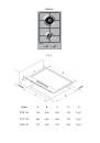
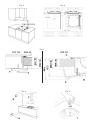
Fixing the cooktop (fig.7):
To fix the cooktop in the housing, proceed as follows:
-
Position the special gasket supplied [C] along the outer perimeter of the worktop, following the
diagram shown in fig.4, so that the ends of the gasket meet exactly without overlapping.
-
Position the cooktop into the worktop, taking care to ensure it is placed exactly in the centre.
-
Fix the cooktop to the worktop using the special brackets supplied [A], as shown in fig.7.
Correct installation of the sealing gasket ensures complete protection against infiltration of liquids.
Installation area and removal of combustion fumes
The appliance must be installed and operated in suitable areas, and in compliance with current laws.
The installation technician must observe current laws governing ventilation and removal of combustion fumes
Please remind that the air required for combustion is 2m
3
/h per kW of power (gas) installed.
Installation area
In the room where the gas appliance is installed, there must be a sufficient natural air supply to
allow the gas to burn correctly (in conformity of currents laws).
The natural flow of air must take place through an opening made on an outside wall of the room
and having a working section of at least 100 cm
2
(A). In the case of appliances without safety
valves, this opening must have a minimum working section of 200 cm
2
(fig.8).
This opening must be made in such a way that it cannot be obstructed from inside or outside.
It should be positioned near floor level, preferably on the side opposite the fume exhaust devices.
If it is not possible to make the necessary openings, the air can be supplied from an adjacent, suitably
ventilated room, as long as this room is not a bedroom, a dangerous area or a lowpressure area.
Removal of combustion fumes
Combustion fumes produced by gas appliances must be removed by means of a hood connected
directly either to an exhaust duct or to the outside (fig.8).
If a hood cannot be installed, an electric extractor fan must be fitted to the outside wall or the window.
This electric extractor fan must have a sufficient capacity to guarantee a change of air of the
kitchen of at least 3-5 times its volume.
Components shown in fig.8:
A Opening for air supply
C Hood for exhaust removal of combustion fumes
E Electric extractor fan for removal of combustion fumes
Connection to gas supply
Before installation, make sure the type and pressure of the local gas supply are compatible with the
cooktop settings.
To do this, check the data on the appliance data plate on the cooktop as well as on this handbook.
The gas connection must be carried out by a qualified technician in compliance with local current laws.
If using metal hoses, ensure these do not come into contact with any movable parts and are at no
point crushed.
Carry out the connection in such a way as does not cause any stress whatsoever on the appliance.
The gas supply connector is threaded G½” (fig.12).
For ISO R7 connections, the gasket is not required.
For ISO R228 connections, the washer supplied must be fitted.
After connection operations, check for leaks using a soapy solution.
10