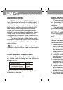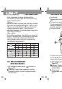
1) LCD will display
OL
if failing to insert
temperature sensor into temperature gear. Clamp
meter will display current indoor temperature after
user inserting temperature sensor.
2) Temperature protection gear of the machine
is plug-in resistance (R59) of 1K
. Electrified
conductor cannot be inserted into input jack
during temperature measurement to avoid
resistance burnout.
A
A
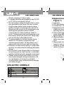
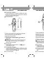
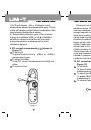
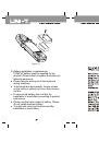
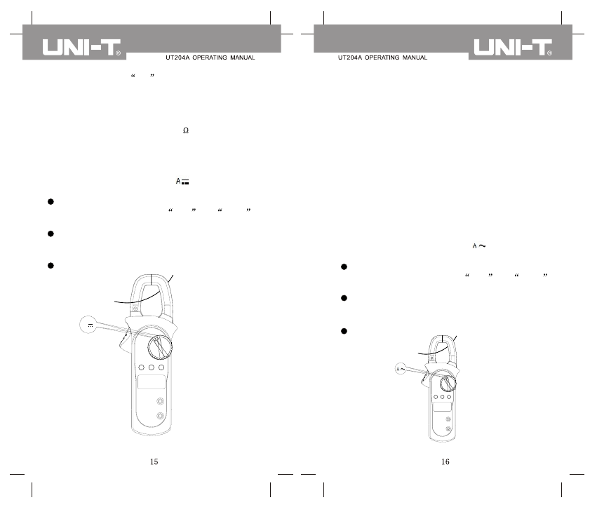
9. DC current measurement ( ) (shown in
Figure 11)
To set knob.
To place function knob to
40A
or
600A
measurement gear.
To select functions.
To set DC current measurement to initially set
value.
To connect load.
Figure 11
Please do not loosen trigger suddenly. As a
sensitive device, Hall element will be sensitive to
heat and mechanical stress to different extents
except magnetic sensitivity. Collision will cause
short-term reading variation. Please open the
clamp head by pressing trigger then fetch
measured conductor by clamp head and loosen
trigger slowly until it is closed completely. Please
check if measured conductor is in the middle of
clamp head or not. Additional error may be caused
if failing to place it in the middle of clamp head.
Clamp meter can measure a current conductor
once and measurement reading error may be
caused if measuring two or more current
conductors at the same time.
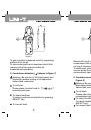
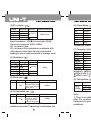
10. AC current measurement ( ) (shown in
Figure 12)
To set knob.
To place function knob to
40A
or
600A
measurement gear.
To select functions.
To press SELECT key for AC current
measurement;
To connect load.
Figure 12