Chapter 2 Hardware Installation and Connections
IES-5000 Series User’s Guide
49
Use the following procedure for this MDF installation scenario.
1
Connect the Telco-50 connector end of the cable you want for DSL service to the Telco-
50 connector labeled
USER
on the splitter chassis rear panel.
2
Connect the wiring on the other side of the Telco-50 cable to the upper ports of MDF 3
using a punch-down tool.
3
Connect the telephone wiring from the end-user’s DSL modem(s) to the lower ports of
MDF 3.
4
Connect the Telco-50 connector end of the cable you want for phone service to the
Telco-50 connector labeled
CO
on the splitter chassis rear panel.
5
Connect the wiring on the other side of the Telco-50 cable to the lower ports of MDF 2
using a punch-down tool.
6
Connect the upper ports of MDF 2 to the lower ports of MDF 1 using telephone wires.
7
Connect the upper ports of MDF 1 to the telephone company.
8
Telephone subscribers only (non-DSL subscribers) retain connections to the lower ports
of MDF 1.
9
Change the wiring from MDF 1 to MDF 3 for telephone subscribers who want DSL
service.
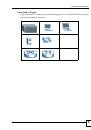
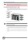
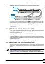
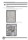
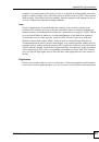
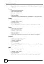
2.5.4.3 Installation Scenario C
Phone service is also available but there are two MDFs; one for end-user telephone line
connections and the other one for CO telephone wiring connections (see the following figure).
This installation scenario does not apply to G.SHDSL connections.
"
Users A and B have telephone service only.
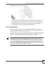
Figure 29
Two Separate MDFs for End-user and CO Connections
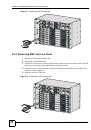
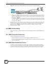
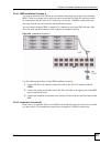
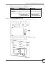
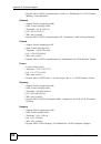
This installation scenario requires four MDFs. Please refer to the following figure for the DSL
connection schema.
• MDFs 1 and 2 are the two original MDFs.
• MDFs 3 and 4 are two additional MDFs you need.