Chapter 2 Hardware Installation and Connections
IES-5000 Series User’s Guide
56
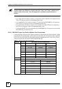
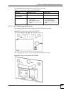
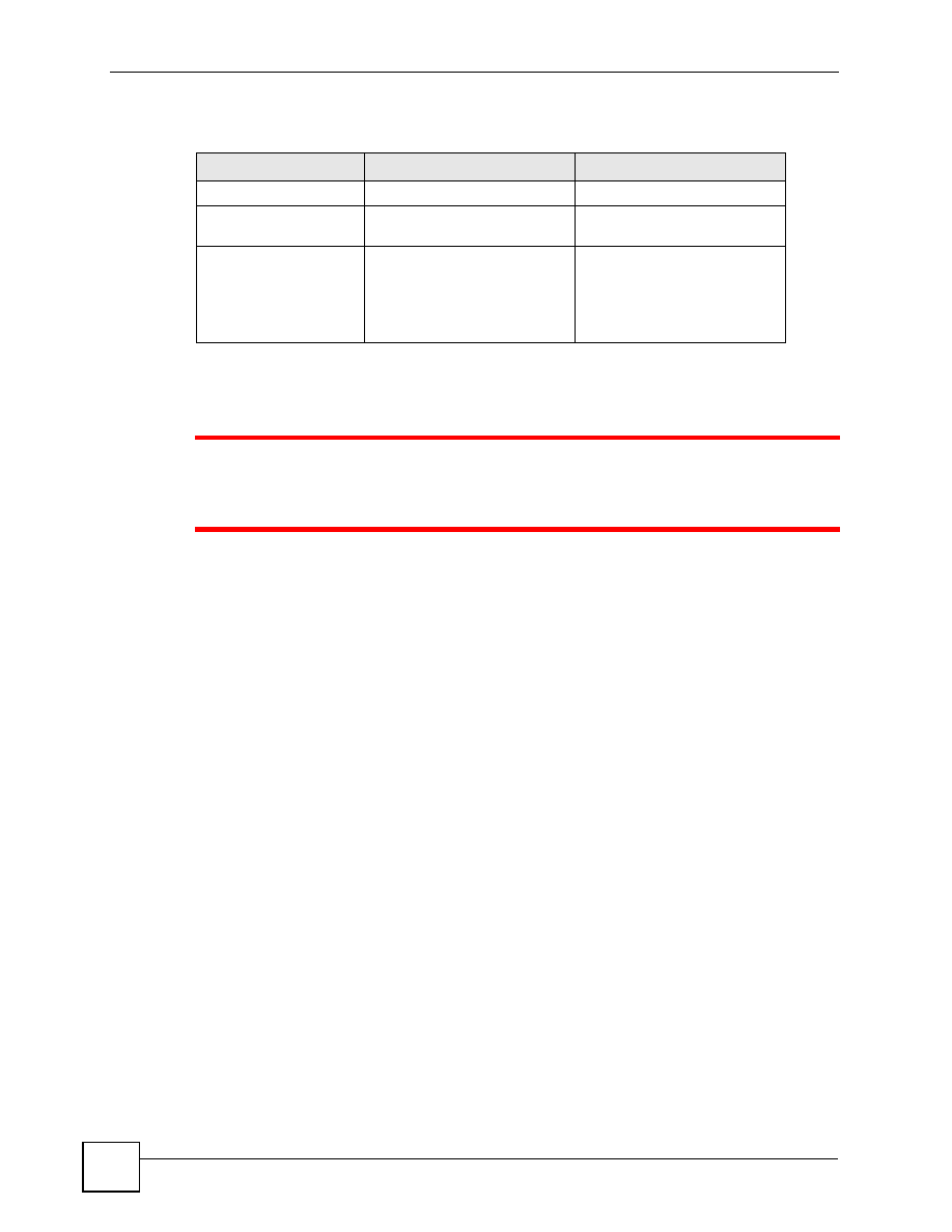
The following table describes the two types of power module.
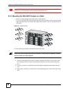
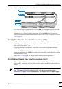
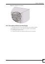
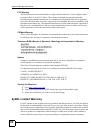
2.6.2 Procedure to Connect the Power: IES-5000M
1
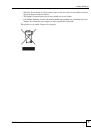
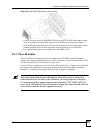
When installing the IES-5000M power wires, push the wires firmly into the
terminals as deep as possible and make sure that no exposed (bare) wires
can be seen or touched.
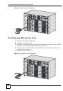
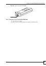
Use two wires to connect to each power module; one for the positive terminal and one for the
negative terminal.
1
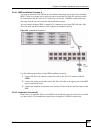
Use a screwdriver to loosen the power module screws.
2
Slide the power module out of the housing. Ensure that the terminal screws are
sufficiently loose for the power wires to be inserted.
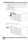
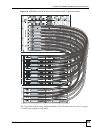
3
Connect a power wire to the negative power terminal on the front of the power module,
and tighten the terminal screws.
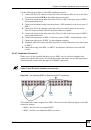
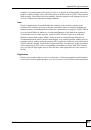
4
Connect the other end of the power wire to the –48 V terminal on the power supply.
5
Connect a power wire to the positive power terminal on the front of the power module,
and tighten the terminal screw.
6
Connect the other end of the power wire to the ground terminal on the power supply.
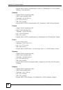
7
Push the power module back in and tighten the screws.
8
Repeat the previous steps for the second power supply module.
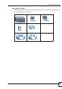
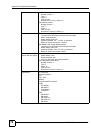
Table 4
Power Module Differences (IES-5005M)
FEATURE
ORIGINAL TYPE
NEWER TYPE
Supplied fuse rating
8A
15A
Number of supported 72-
port line cards.
2
4
Identifying features
•
Power wires clip into slots at
the top of the module’s front
panel.
•
Power block is situated
inside the module.
•
Power wires connect to
lower part of module’s front
panel.
•
Power block is situated on
module’s front panel and is
removable.