11
iNUKE NU6000DSP/NU3000DSP/NU1000DSP User Manual
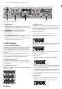
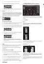
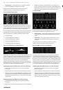
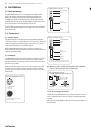
Stereo mode routes the signal from both the A and B inputs through a single
series of DSP modules. Each DSP module processes both the A and B signals
with identical, linked settings. The linked Delay and Limit parameters can be
controlled from Stereo mode’s consolidated Channel A+B control window
(which displays automatically when Stereo mode is selected).
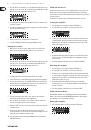
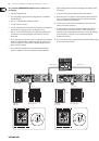
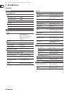
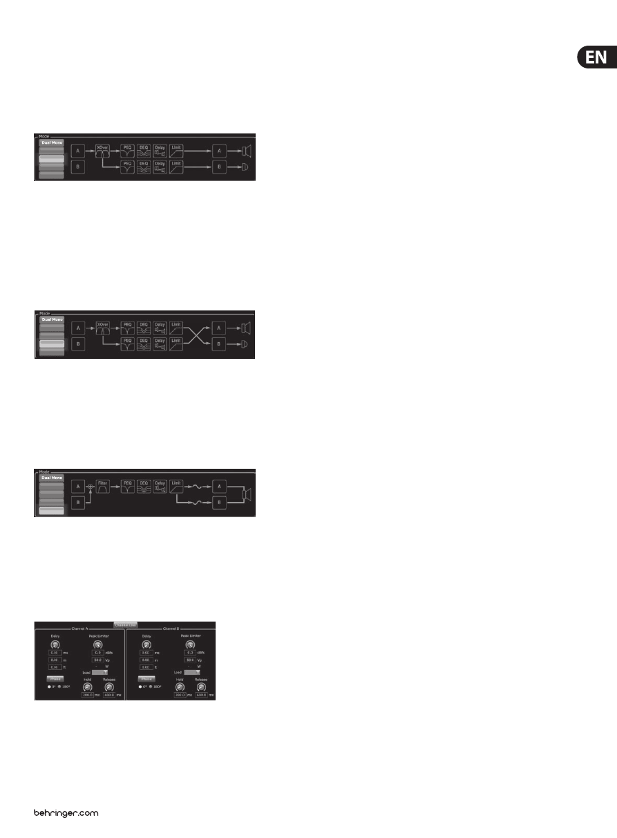
Bi-Amp 1
Bi-Amp 1 mode splits the Channel A input signal in the XOver DSP module at
a programmable frequency point, and then routes the resulting high and low
frequency signals through a parallel chain of DSP modules with independent
equalization, delay, and limiter settings. The Delay and Limit modules for the split
high and low frequency signals can be linked and programmed with identical
settings by clicking on the Channel Link button below the Mode window. In
Bi-Amp 1 mode, Output A routes low frequencies to a low-range speaker, while
Output B connects to a high-frequency transducer.
Bi-Amp 2
Bi-Amp 2 mode operates identically to Bi-Amp 1 mode, except that the signals
are swapped between Outputs A and B (i.e., Output B handles low frequencies
while Output A handles high frequencies). The swapped A and B output routing
allows the user to quickly correct reversed high/low speaker connections without
having to physically access the amplifier’s back panel and manually change the
speaker connection.
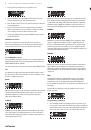
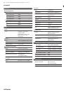
Bridge
Bridge mode combines the signals from Inputs A and B into a blended mono
signal and then routes the resulting mono signal through a single chain of
DSP modules, leading to a combined mono output. The mono output signal is
identical at Outputs A and B, and the amplifier responds to a single combined
speaker load.
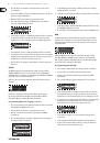
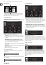
Delay/Peak Limiter
Channel Link
In Dual Mono, Bi-Amp 1, and Bi-Amp 2 modes, the Channel Link virtual button
will appear just above the Delay and Peak Limiter controls. When you click on
the Channel Link virtual button, the button will light up, and the Delay and Peak
Limiter controls for both channels will display identical values.
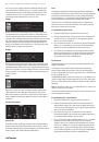
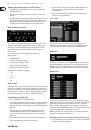
Delay
The Delay function digitally slows the final signal output from the amplifier by a
programmable amount (expressed as either distance or time). This signal delay helps
prevent phase and synchronization problems caused by sound traveling through
air over long distances, e.g., between speaker arrays separated by long distances or
between a performance stage and distant sound reinforcement speakers.
The Delay controls also simultaneously display the amount of signal delay in
milliseconds (ms), meters (m), and feet (ft), which can be useful if you already
know the precise distance between speakers.
Programming signal delay
1. Program the signal delay by using either of these two methods:
a) Rotate the Delay virtual knob clockwise until you achieve a suitable amount
of signal delay. The ms, m, and ft text boxes will each display equivalent
values as you rotate the virtual knob.
b) Type a delay value directly into one of the text boxes below the Delay virtual
knob (ms, m, or ft, depending on your preference). The Delay virtual knob
will rotate to a position matching the delay value you have entered.
2. Choose between 0° and 180° phase either by clicking on the Phase virtual
button or by clicking directly on 0° or 180° directly below the virtual button.
When the Phase virtual button is engaged, the virtual button will light
yellow and the indicator next to 180° will light up.
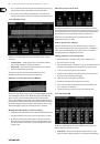
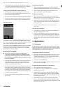
Peak Limiter
The Peak Limiter helps protect your speakers by preventing signal spikes at the
amplifier's output stage.
The Peak Limiter controls include a dedicated virtual knob with matching
numerical displays in dBfs (decibels relative to full scale), Vp (Voltage(peak)),
as well as a rating in Watts, which appears only when you choose an Ohm setting
from the Load pulldown menu.
The BEHRINGER Amp Remote software also allows you to see the amplifier's total
output as a rating in Watts. This Watt rating allows you to connect speakers with
lower power ratings and then adjust the limiter to match the speakers' maximum
Watt rating.
Note:
the Amp Remote software does not automatically detect or show the total
speaker load connected to the amplifier.
Controls for Hold and Release times appear near the bottom of the window, each
with a matching numerical display.
Programming the output limiter
1. Program the output limiter by using either of these two methods:
a) Rotate the Peak Limiter virtual knob counter-clockwise until you find an
adequate limiter setting for your sound system. The dBfs (decibels relative
to full scale) and Vp (Voltage [peak]) text boxes will each display equivalent
values as you rotate the virtual knob.
b) Type a limiter value directly into one of the text boxes below the Peak
Limiter virtual knob (dBfs or Vp). The Peak Limiter virtual knob will rotate to
a position matching the delay value you have entered.
2. Choose a Load value from the Load pulldown menu (none, 2, 4, 8, or 16 Ohms)
that matches the total combined load of all speakers connected to the
amplifier's outputs. If your combined speaker load in Ohms does not exactly
match 2, 4, 8, or 16 Ohms, choose the next lower Ohm setting from the Load
pulldown menu (i.e., if your total combined speaker load equals 4.25 Ohms,
select the 4 Ohm setting). When you select a Load setting, an additional Watt
rating for the limiter will appear above the Load pulldown menu.
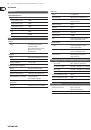
Stereo
Bi-Amp 1
Bi-Amp 2
Bridge
Stereo
Bi-Amp 1
Bi-Amp 2
Bridge
Stereo
Bi-Amp 1
Bi-Amp 2
Bridge