7
iNUKE NU6000DSP/NU3000DSP/NU1000DSP User Manual
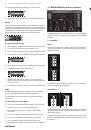
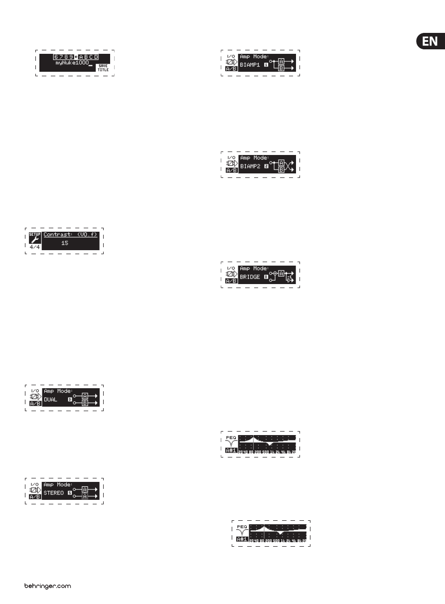
2. Press the SELECT encoder knob to access the editing screen.
3. Choose the backwards arrow by turning the SELECT knob and press it to
delete the existing characters of the current preset name.
4. Rotate the SELECT encoder to select new characters from the row above the
current amplifier name.
5. Insert selected characters into the new amplifier name by pressing the
SELECT encoder knob. Once you select and insert a character, the editing
cursor will change direction and advance from left to right.
6. Save the new amplifier name by pressing the DOWN arrow key to activate
the SAVE TITLE function.
SETUP 4/4: Contrast
The Contrast screen allows you to adjust the LCD screen’s contrast level.
The Contrast parameter ranges from 1–30, with 30 representing maximum
contrast. Rotate the SELECT encoder knob to adjust the Contrast setting.
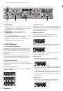
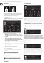
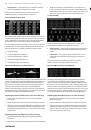
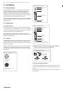
3.2.3 PROCESS screens
Pressing the PROCESS button opens up the various screens that determine the
signal path setup and that control processing parameters for the DSP modules:
I/O, PEQ, XOVER, DEQ, DELAY, and LIMIT.
You can move between top-level module screens by pressing the PROCESS button.
I/O
The I/O module sets up the signal routing inside the DSP from input to output.
Press and rotate the SELECT encoder knob to choose between dual mono, stereo,
bi-amped, or bridged routing options.
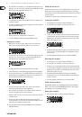
DUAL
DUAL (dual mono) mode routes each channel input, A and B, through completely
separate parallel signal paths with independent outputs for each channel.
Each channel may be processed with its own unique filter, equalization,
signal delay, and limiter settings.
STEREO
STEREO mode routes the signal from both the A and B inputs through a single
series of DSP modules. The parallel DSP modules process the A and B signals
with identical, linked settings (only module “A” parameter settings appear on
subsequent DSP module screens).
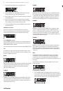
BIAMP1
BIAMP1 mode splits the Channel A input signal at a programmable frequency
point, and then routes the resulting high and low frequency signals through
a parallel chain of DSP modules with independent equalization, signal delay,
and limiter settings. In BIAMP1 mode, Output A routes low frequencies to a
low-range speaker, while Output B connects to a high-frequency transducer.
BIAMP2
BIAMP2 mode operates identically to BIAMP1 mode, except that the output
signals are swapped between Outputs A and B (i.e., Output B handles low
frequencies while Output A handles high frequencies). The swapped A and B
output routing allows the user to quickly correct reversed high/low speaker
connections without having to physically access the amplifier’s back panel and
manually change the speaker connection.
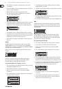
BRIDGE
BRIDGE mode combines the signals from Inputs A and B into a blended mono
signal and then routes the resulting mono signal through a single chain of
DSP modules, leading to a combined mono output. The mono output signal is
identical at Outputs A and B, and the amplifier responds to a single combined
speaker load.
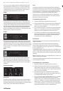
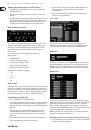
PEQ
The PEQ module deploys up to eight EQ bands for precise sound sculpting.
The EQ bands can each be switched between low shelving, high shelving,
and parametric modes. For the high shelving and low shelving EQ bands,
the LS12 and HS12 settings provide steeper equalization curves than the LS6 and
HS6 settings.
The main PEQ screen displays the composite equalization curve across the
frequency spectrum.
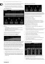
Programming equalizers
1. Choose individual equalizers by rotating the SELECT encoder knob. As you
rotate the SELECT encoder knob, dotted vertical lines will appear at different
points within the frequency spectrum, and the EQ band name will appear in
the lower-left corner of the screen (e.g., A#1, A#2, B#1, B#2, and so on).