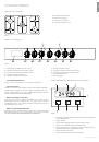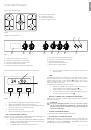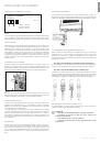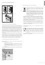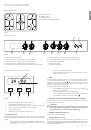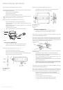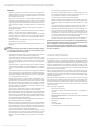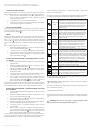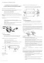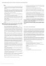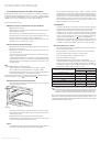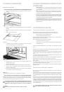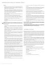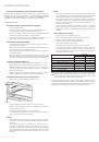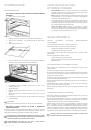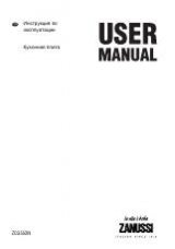
GAS BURNER PLATE
SR – Normal gas burner;
R – Rapid gas burner;
A – Auxiliary gas burner;
TC – a gas burner with three rows of fl ames.
Figure 1
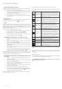
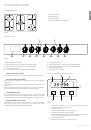
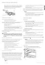
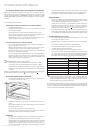
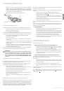
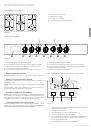
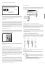
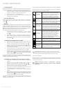
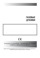
CONTROL PANEL
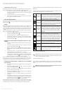
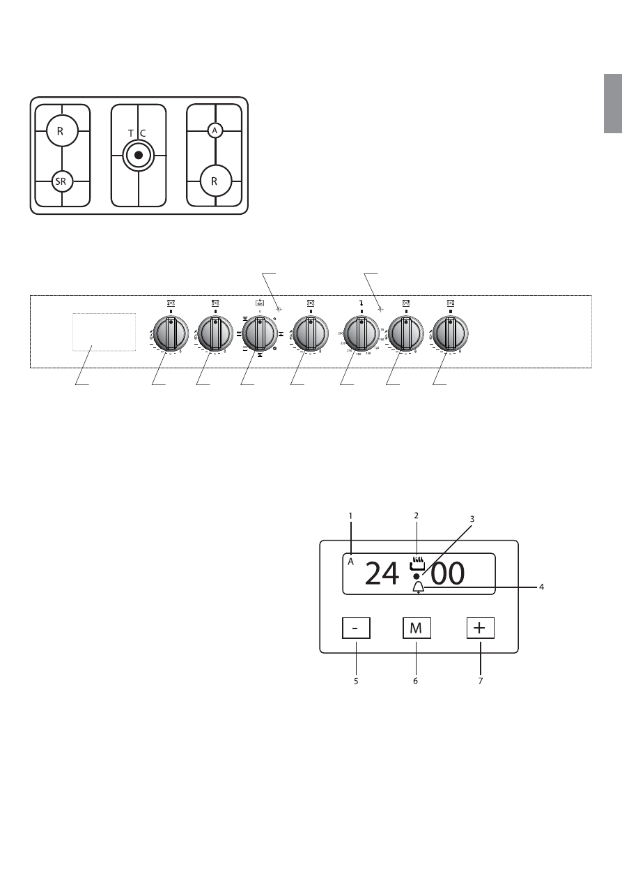
DIGITAL DISPLAY WITH TOUCH CONTROL
GB
17
PP96GEE50 RANGE COOKERS
•
POWER SUPPLY INDICATOR (RED)
If the indicator is lit, it means the oven is functioning properly and is switched on.
•
OVEN IGNITION INDICATOR (AMBER)
When this indicator is switched on, it means that the oven is in the preliminary
heating phase.
Когда он выключен, это означает, что духовой шкаф достиг установленной тем-
пературы.
Когда он периодически включается и выключается, это означает, что температу-
ра в духовом шкафу постоянно поддерживается на заданном уровне.
• OVEN
THERMOSTAT
KNOB
The oven thermostat controls the cooking temperature in all settings, including
those for the grill. Turning the corresponding knob clockwise will allow you to set the
temperature inside the oven at the required level within the range of 50°С и 250°C.
•
OVEN PROGRAMME CONTROL KNOB
The knob will activate the required setting needed for cooking. The description
of the settings, and tips how to choose them, can be found in the chapter
“MULTIFUNCTIONAL ELECTRIC OVEN WITH IN-BUILT FAN”.
PP96GEE50 RANGE COOKERS
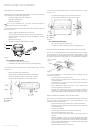
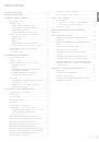
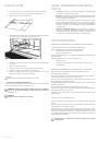
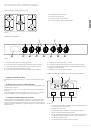
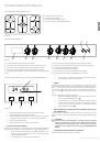
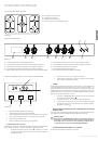
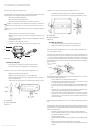
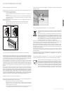
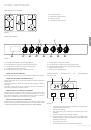
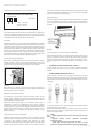
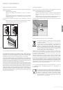
Figure 2
A – digital display with touch control;
B — left front burner knob – used to switch on and adjust the fl ame
C — left rear burner knob – used to switch on and adjust the fl ame;
D — oven setting control knob;
E — central burner knob – used to switch on and adjust the fl ame;
F — oven thermostat handle;
G — right rear burner knob – used to switch on and adjust the fl ame;
H — right front burner knob – used to switch on and adjust the fl ame;
I — power supply indicator (red);
J — oven ignition indicator (amber).
А
B
C
D
I
J
E
F
G
H
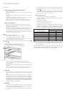
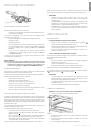
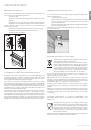
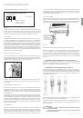
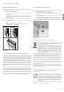
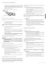
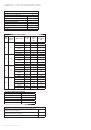
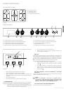
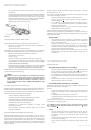
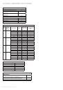
Figure 3
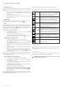
1. An automatic programme is in use (in some models you will see an
inscription “Auto” instead of the letter A).
2.
Manual control setting.
3.
This indicator fl ashes when the timer is being set up
4.
This indicator shows when a timer is activated.
5.
A button used to decrease the time when a timer is being set. It is also used
to choose an audio signal level (three levels are available).
6.
Setting selection button.
7.
Button used to increase the time, when a timer is set.