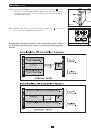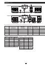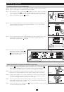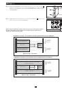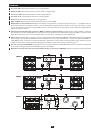
PDUB15
PDUB20
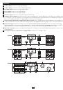
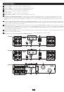
PDUB30
12A MAX.
12A MAX.
OUTPUT
12A MAX.
12A MAX.
OUTPUT
TO UPS OUTPUT
UTILITY
UTILITY
UPS
UPS
AVAILABLE
MAINTENANCE BYPASS
AVAILABLE
CONNECT UPS
LINE CORD HERE
15A MAX.
15A MAX.
OUTPUT
16A MAX.
16A MAX.
OUTPUT
TO UPS OUTPUT
UTILITY
UTILITY
UPS
UPS
AVAILABLE
MAINTENANCE BYPASS
AVAILABLE
CONNECT UPS
LINE CORD HERE
OUTPUT
24A MAX.
OUTPUT 20A MAX.
LOAD1
LOAD2
20A OUTPUT
BREAKERS
PUSH TO RESET
TO
UPS OUTPUT
UTILITY
30A
30A
UTILITY
UPS
UPS
AVAILABLE
MAINTENANCE BYPASS
AVAILABLE
CONNECT UPS
LINE CORD HERE
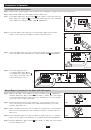
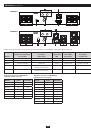
1
1
6
6
7
7
9
9
3
9
7
11
6
10
1
2
2
11
8
8
8
10
10
18
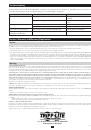
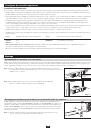
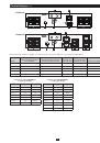
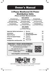
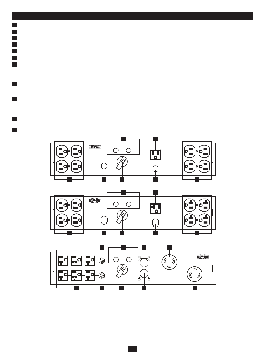
Caractéristiques
1
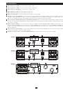
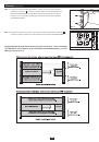
Sorties CA 5-15R : se connectent aux fiches de l’équipement 5-15P.
2
Sorties CA 5-20R : se connectent aux fiches de l’équipement 5-15P ou 5-20P.
3
Sorties CA L5-30R : se connectent aux fiches de l’équipement L5-30P.
4
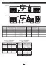
Sorties CA C13 : se connectent aux fiches de l’équipement C14.
5
Sorties CA C19 : se connectent aux fiches de l’équipement C20.
6
Entrée de source de l’UPS : se connecte à la sortie compatible du système UPS.
7
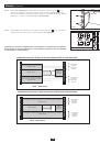
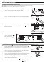
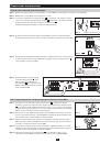
Sectionneur de dérivation pour maintenance : sélectionne la source d’alimentation qui alimente la charge – soit la source de l’UPS ou la source de secteur.
Lorsque le sectionneur est réglé sur « Utility » (Secteur), l’équipement connecté reçoit l’alimentation secteur CA du PDU, mais l’équipement ne recevra pas
l’alimentation de secours de la batterie de l’UPS dans le cas d’une panne du secteur. Voir le « Fonctionnement manuel de la dérivation » pour plus de renseigne-
ments.
8
Voyants de diagnostic (UPS disponible et dérivation pour maintenance disponible) : Un voyant vert « UPS Available » (UPS disponible) s’allumera lorsque
la source de l’UPS est connectée et sous tension. Un voyant jaune « Maintenance Bypass Available » (Dérivation pour maintenance disponible) s’allumera lor-
sque la source de secteur est connectée et sous tension.
9
Entrée de source de secteur : se connecte à la source d’alimentation secteur. Les modèles PDUB15, PDUB20 et PDUB30 possèdent chacun un cordon et une
fiche d’entrée fixe. Le modèle PDUBHV10 possède une entrée C14 et le modèle PDUBHV20 possède une entrée C20. Les modèles PDUBHV10 et PDUBHV20
comprennent une bretelle d’extension et peuvent être utilisés avec un cordon d’alimentation fourni par l’utilisateur. (Voir ci-dessous pour une sélection des cor-
dons d’alimentation compatibles Tripp Lite.)
10
Sortie de connexion de l’UPS : se connecte au cordon d’alimentation de l’entrée de l’UPS. L’utilisateur doit apparier le cordon d’alimentation de l’entrée de
l’UPS avec un modèle de PDU compatible.
11
Disjoncteurs de sortie CA de dérivation de 20 A (PDUB30 uniquement) : contrôlent l’alimentation des sorties de PDU.