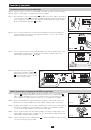
Инструкция для TRIPP LITE PDUBHV10, PDUBHV20

(скачивание инструкции бесплатно)
Формат файла: PDF
Доступность: Бесплатно как и все руководства на сайте. Без регистрации и SMS.
Дополнительно: Чтение инструкции онлайн
background image

Mount in top or 
bottom holes.

2

Important Safety Warnings

SAVE THESE INSTRUCTIONS

This manual contains important instructions and warnings that should be followed during the installation and operation of this product.

•   Install the PDU indoors, away from excess moisture or heat, direct sunlight, dust or conductive contaminants. Do not install the PDU near 

magnetic storage media, as this may cause data corruption.

•   Only operate the PDU at indoor temperatures between 32° F and 104° F (0 °C and 40° C). For best results, maintain indoor temperatures 

between 62° F and 84° F (17° C and 29° C). For proper ventilation, leave adequate space around all sides of the PDU.

•   Use of this equipment in life support applications where failure of this equipment can reasonably be expected to cause the failure of the life 

support equipment or to significantly affect its safety or effectiveness is not recommended. Do not use this equipment in the presence of a 
flammable anesthetic mixture with air, oxygen or nitrous oxide.

•   Do not connect the PDU to an ungrounded outlet or to adapters that eliminate the connection to ground. The ground connections are provided 

for your safety. If the provided plug does not fit your outlet, have a compatible grounded outlet installed by a qualified electrician.

•   The PDU must be installed near the wall outlet and all plugs must be readily accessible for disconnection.

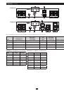
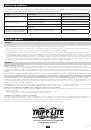
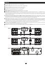
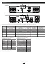
•   The PDU must be connected to a wall outlet that is protected by an overcurrent device with the rating shown in the table below:

  Model   

Overcurrent Rating of Protection Device 

Model 


Overcurrent Rating of Protection Device

  PDUB15 

20A 


PDUBHV10 

20A (

c

TUV

us

) or 16A (CE) 

PDUB20 

20A 


PDUBHV20 

20A (

c

TUV

us

) or 16A (CE) 

PDUB30 

30A

•   Caution! Risk of electrical shock! The PDU is supplied by more than one power source. All power sources must be disconnected to de-

energize the unit before servicing.

•   Do not open the PDU for any reason. There are no user-serviceable parts inside.
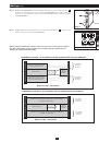
Mounting

Mounting (2-Post or 4-Post Racks)

Mount the equipment in either a 2-post or 4-post open frame rack or rack enclosure. The user must determine the fitness of hardware and 
procedures before mounting. The procedures described in this manual are for common rack and rack enclosure types and may not be appropriate 
for all applications.

 Note: Mounting procedures are the same for both 2-post and 4-post rack installation.

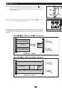
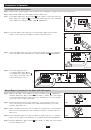
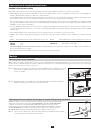
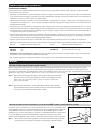
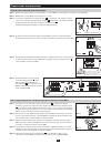
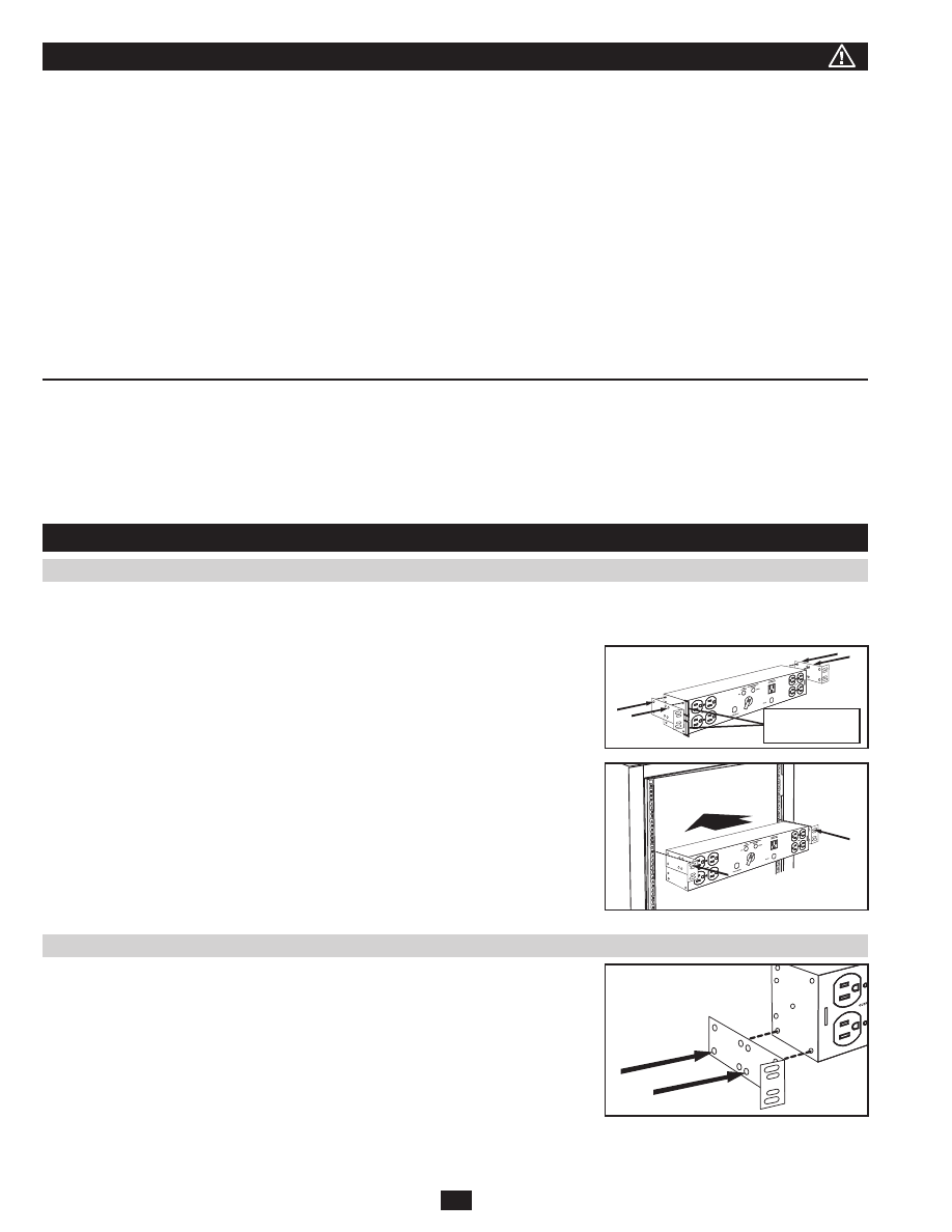
Step 1.  Attach the mounting ears to the mounting holes of the PDU using the screws provided.  

The ears should face forward. 

Note: The top or bottom mounting holes of the PDU can  

be used.

Step 2.  Attach the PDU to the rack with user-provided screws, nuts and washers. Insert the  

screws through the mounting ears and into the rack rails.

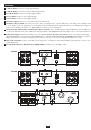
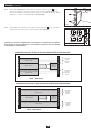
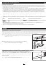
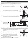
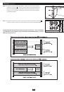
Mounting in the Same Rack Space as a UPS System (4-Post Racks)

The Hot-Swap PDU can be mounted in the same rack space as a UPS system when the UPS 
system is mounted using Tripp Lite’s 4POSTRAILKIT. (4POSTRAILKIT is included with 
most Tripp Lite UPS systems and is also sold separately. Refer to the UPS system manual or 
4POSTRAILKIT manual for UPS system mounting instructions. The procedure for mounting 
the rear of the 4POSTRAILKIT mounting shelves to the rack will differ slightly, as shown in this 
section.)
Step 1.  Attach the mounting ears to the lower mounting holes of the unit using the screws  
 

provided. The ears should face forward.

Step 1

Step 1

Step 2

1
2
3
4
5
6
7
8
9
10
11
12
13
14
15
16
17
18
19
20
21
22
23
24
25
26
27
28
Оглавление инструкции
  • Страница 1 из 29
    pr ch re R W od an gi uc ce ste eg arr t— to r o is a w w nli tra nty w in n w. a e tio tri F to n pp R da : lit EE y f e. T o co ri r a m pp /w L ar ite ra nt y Owner’s Manual Hot-Swap PDU with Maintenance Bypass Switch Models: PDUB15, PDUB20, PDUB30, PDUBHV10, PDUBHV20 Important Safety Warnings 2
  • Страница 2 из 29
    Important Safety Warnings SAVE THESE INSTRUCTIONS This manual contains important instructions and warnings that should be followed during the installation and operation of this product. • Install the PDU indoors, away from excess moisture or heat, direct sunlight, dust or conductive contaminants.
  • Страница 3 из 29
    Mounting (continued) Step 2. Install 4POSTRAILKIT into the rack using only the top mounting hole A at each side of the rear of the 4POSTRAILKIT mounting shelves. (The screws at the front of the shelves will not change from the standard procedure shown in your UPS or 4POSTRAILKIT manual.) A B Step 2
  • Страница 4 из 29
    Features 1 5-15R AC Outlets: Connect to 5-15P equipment plugs. 2 5-20R AC Outlets: Connect to 5-15P or 5-20P equipment plugs. 3 L5-30R AC Outlets: Connect to L5-30P equipment plugs. 4 C13 AC Outlets: Connect to C14 equipment plugs. 5 C19 AC Outlets: Connect to C20 equipment plugs. 6 UPS Source
  • Страница 5 из 29
    Features (continued) 8 PDUBHV10 10 UPS MAINTENANCE BYPASS AVAILABLE AVAILABLE UPS CONNECT UPS LINE CORD HERE UTILITY UTILITY TO UPS OUTPUT OUTPUT 10A MAX. 4 OUTPUT 10A MAX. 6 7 9 8 PDUBHV20 4 10 UPS MAINTENANCE BYPASS AVAILABLE AVAILABLE UPS CONNECT UPS LINE CORD HERE UTILITY UTILITY TO UPS OUTPUT
  • Страница 6 из 29
    Connection & Operation Input/Output Power Connections Step 1. Shut down the equipment plugged into the UPS system and unplug the equipment cables from the UPS system. Step 2. Shut down the UPS system and unplug it from the utility source. Step 3. Set the PDU’s Maintenance Bypass Switch A to the
  • Страница 7 из 29
    Troubleshooting Use the following chart to make minor adjustments or attempt to solve problems. Do not attempt to open the PDU, as there are no user-serviceable parts inside. If problems persist after troubleshooting, please visit www.tripplite.com/support. Problem Possible Cause Possible Solution
  • Страница 8 из 29
    Manual del propietario PDU con cambio en operación e interruptor de rodeo de mantenimiento Modelos: PDUB15, PDUB20, PDUB30, PDUBHV10, PDUBHV20 Advertencias de seguridad importantes 9 Montaje 9 Características 11 Conexión y operación 13 Solución de problemas 14 Servicio y garantía 14 English 1
  • Страница 9 из 29
    Advertencias de seguridad importantes GUARDE ESTAS INSTRUCCIONES Este manual contiene instrucciones y advertencias importantes que deben seguirse durante la instalación y operación de este producto. • Instale la PDU en interiores, alejada de la humedad o el calor excesivos, la luz solar directa,
  • Страница 10 из 29
    Montaje (continuación) Paso 2. Instale el 4POSTRAILKIT en el rack usando solo el orificio de montaje superior A que se encuentra a cada lado en la parte posterior de los estantes de montaje 4POSTRAILKIT. (La ubicación de los tornillos en la parte frontal de los estantes no será distinta a la del
  • Страница 11 из 29
    Características 1 Tomacorrientes de CA 5-15R: para conectar clavijas de equipos 5-15P. 2 Tomacorrientes de CA 5-20R: para conectar clavijas de equipos 5-15P ó 5-20P. 3 Tomacorrientes de CA L5-30R: para conectar clavijas de equipos 5-30P. 4 Tomacorrientes de CA C13: para conectar clavijas de equipos
  • Страница 12 из 29
    Características (continuación) 8 PDUBHV10 10 UPS MAINTENANCE BYPASS AVAILABLE AVAILABLE UPS CONNECT UPS LINE CORD HERE UTILITY UTILITY TO UPS OUTPUT OUTPUT 10A MAX. 4 OUTPUT 10A MAX. 6 7 9 8 PDUBHV20 4 10 UPS MAINTENANCE BYPASS AVAILABLE AVAILABLE UPS CONNECT UPS LINE CORD HERE UTILITY UTILITY TO
  • Страница 13 из 29
    Conexión y operación Conexiones eléctricas de entrada/salida Paso 1. Apague los equipos conectados en el sistema UPS y desenchufe los cables conectados en el UPS. Paso 2. Apague el sistema UPS y desenchúfelo de la fuente de red pública. Paso 3. Fije el interruptor de rodeo de mantenimiento A de la
  • Страница 14 из 29
    Solución de problemas Use el siguiente cuadro para realizar ajustes menores o intentar la solución de problemas. No intente abrir la PDU, no tiene partes internas que el usuario pueda reparar. Si los problemas continúan después de la solución de problemas, visite www.tripplite.com/support. Problema
  • Страница 15 из 29
    Guide de l’utilisateur PDU remplaçable à chaud avec un sectionneur de dérivation pour maintenance Modèles : PDUB15, PDUB20, PDUB30, PDUBHV10, PDUBHV20 Consignes de sécurité importantes 16 Montage 16 Caractéristiques 18 Connexion et fonctionnement 20 Dépannage 21 Service et garantie 21 English 1
  • Страница 16 из 29
    Consignes de sécurité importantes CONSERVER CES DIRECTIVES Le présent guide contient des consignes et des mises en garde importantes qui devraient être suivies durant l’installation et le fonctionnement du présent produit. • Installer le PDU à l’intérieur, loin de l’humidité ou de la chaleur
  • Страница 17 из 29
    Montage (suite) Étape 2. Installer le 4POSTRAILKIT sur le bâti en utilisant uniquement le trou de montage supérieur A de chaque côté de l’arrière des étagères de montage 4POSTRAILKIT. (Les vis sur le devant des étagères ne seront pas différentes de la procédure standard indiquée dans le manuel de
  • Страница 18 из 29
    Caractéristiques 1 Sorties CA 5-15R : se connectent aux fiches de l’équipement 5-15P. 2 Sorties CA 5-20R : se connectent aux fiches de l’équipement 5-15P ou 5-20P. 3 Sorties CA L5-30R : se connectent aux fiches de l’équipement L5-30P. 4 Sorties CA C13 : se connectent aux fiches de l’équipement C14.
  • Страница 19 из 29
    Caractéristiques (suite) 8 PDUBHV10 10 UPS MAINTENANCE BYPASS AVAILABLE AVAILABLE UPS CONNECT UPS LINE CORD HERE UTILITY UTILITY TO UPS OUTPUT OUTPUT 10A MAX. 4 OUTPUT 10A MAX. 6 7 9 8 PDUBHV20 10 UPS MAINTENANCE BYPASS AVAILABLE AVAILABLE UPS 4 CONNECT UPS LINE CORD HERE UTILITY UTILITY TO UPS
  • Страница 20 из 29
    Connexion et fonctionnement Connexions d’alimentation d’entrée / de sortie Étape 1. Mettre hors tension l’équipement branché dans le système UPS, puis débrancher les câbles du système UPS. Étape 2. Mettre hors tension le système UPS, puis le débrancher de la source de secteur. Étape 3. Régler le
  • Страница 21 из 29
    Dépannage Utiliser le tableau suivant pour effectuer des réglages mineurs ou tenter de résoudre des problèmes. Ne pas essayer d’ouvrir le PDU, puisqu’il n’y a aucun élément à l’intérieur qui puisse être réparé par l’utilisateur. Si les problèmes persistent après le dépannage, veuillez visiter
  • Страница 22 из 29
    Руководство пользователя Блок PDU с переключателем обходной цепи для «горячей» замены Модели: PDUB15, PDUB20, PDUB30, PDUBHV10, PDUBHV20 Важные меры предосторожности 23 Монтаж 23 Свойства 24 Подключение и эксплуатация 26 Поиск и устранение неисправностей 27 Обслуживание и гарантия 27 English 1
  • Страница 23 из 29
    Важные меры предосторожности СОХРАНИТЕ ЭТИ ПРАВИЛА Данное руководство содержит важные правила безопасности и предупреждения, которые нужно соблюдать во время монтажа и эксплуатации этого продукта. • Блок PDU устанавливается в сухом помещении, которое не содержит токопроводящих веществ и пыли, вдали
  • Страница 24 из 29
    Монтаж (продолжение) Шаг 2. Установить комплект 4POSTRAILKIT в стойку, используя только верхнее монтажное отверстие A с каждой стороны задней части монтажных полок комплекта 4POSTRAILKIT. (Крепление винтами передней части полок не отличается от стандартной процедуры, описанной в руководстве по ИБП
  • Страница 25 из 29
    Свойства 1 Розетки 5-15R: Подключение вилки 5-15P от оборудования. 2 Розетки 5-20R: Подключение вилки 5-15P или 5-20P от оборудования. 3 Розетки L5-30R: Подключение вилки L5-30P от оборудования. 4 Розетки C13 AC: Подключение вилки C14 от оборудования. 5 Розетки C19: Подключение вилки C20 от
  • Страница 26 из 29
    Свойства (продолжение) 8 PDUBHV10 10 UPS MAINTENANCE BYPASS AVAILABLE AVAILABLE UPS CONNECT UPS LINE CORD HERE UTILITY UTILITY TO UPS OUTPUT OUTPUT 10A MAX. 4 OUTPUT 10A MAX. 6 7 9 8 PDUBHV20 10 UPS MAINTENANCE BYPASS AVAILABLE AVAILABLE UPS 4 CONNECT UPS LINE CORD HERE UTILITY UTILITY TO UPS
  • Страница 27 из 29
    Подключение и эксплуатация Подключение силовых входов и выходов Шаг 1. Выключить оборудование, подсоединенное к системе ИБП, и отсоединить его кабели от системы ИБП. Шаг 2. Выключить систему ИБП и отсоединить ее от сети. Шаг 3. Установить переключатель обходной цепи A на блоке PDU в положение
  • Страница 28 из 29
    Поиск и устранение неисправностей Следующая таблица используется для внесения небольших исправлений или попыток решения проблем. Нельзя пытаться открыть блок PDU, поскольку в нем не содержатся части, требующие обслуживания пользователем. Если проблема сохраняется после попыток ее решения, посетите
  • Страница 29 из 29