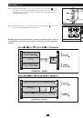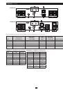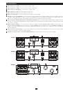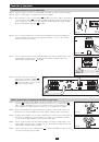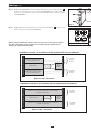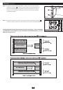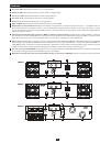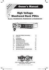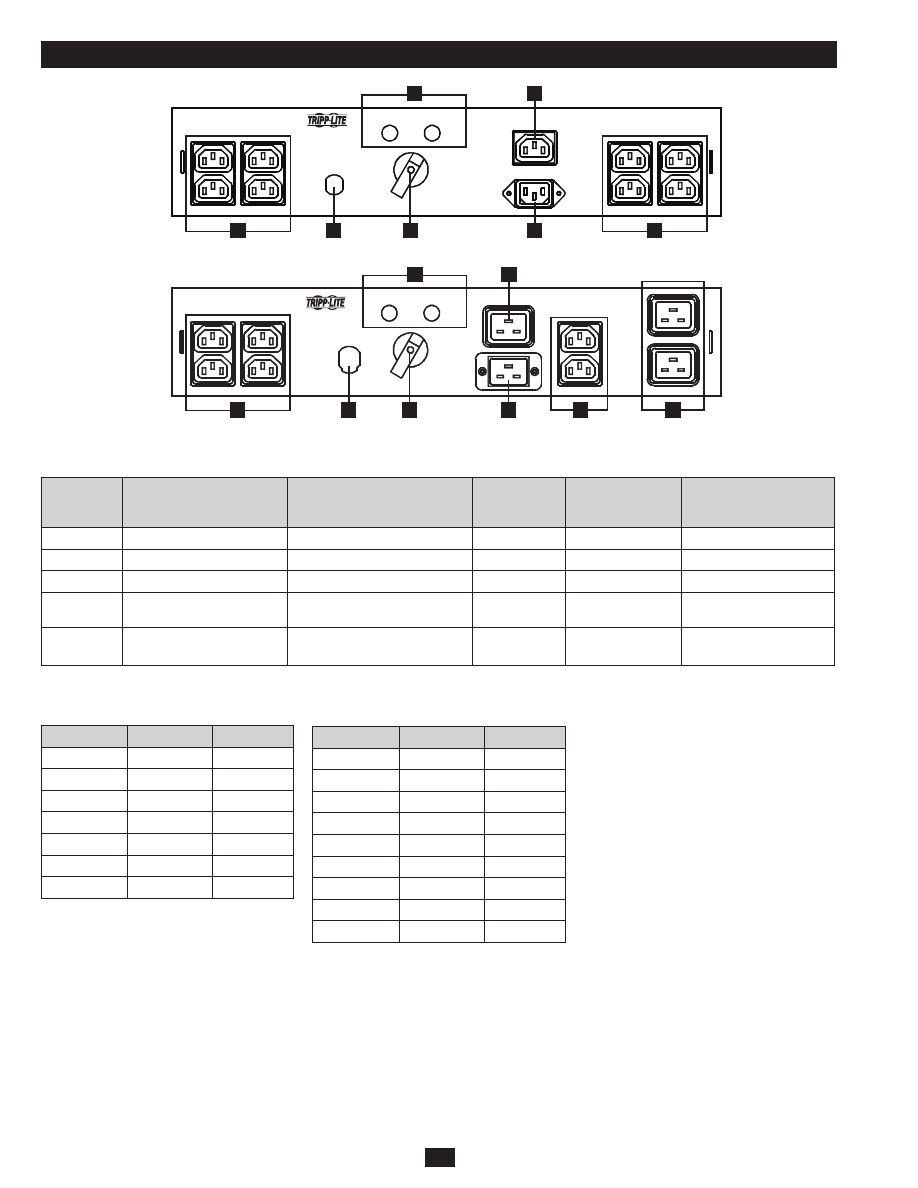
PDUBHV10
PDUBHV20
OUTPUT 10A MAX.
OUTPUT 10A MAX.
TO UPS OUTPUT
UTILITY
UTILITY
UPS
UPS
AVAILABLE
MAINTENANCE BYPASS
AVAILABLE
CONNECT UPS
LINE CORD HERE
OUTPUT 10A MAX.
OUTPUT 10A MAX.
OUTPUT 16A MAX.
TO UPS OUTPUT
UTILITY
UTILITY
UPS
UPS
AVAILABLE
MAINTENANCE BYPASS
AVAILABLE
CONNECT UPS
LINE CORD HERE
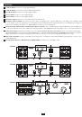
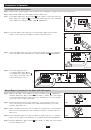
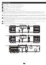
10
10
4
4
4
5
4
6
6
7
7
9
9
8
8
26
Свойства
(продолжение)
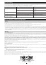
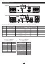
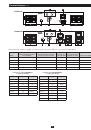
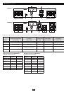
Выбор модели блока PDU, совместимой с входным разъемом системы ИБП и характеристиками мощности:
Модель
Показатели совместимой
системы ИБП
Вилка сетевого
источника/
длина шнура
Розетка для
подключения
ИБП
Вилка подклю
чения к ИБП /
длина шнура
Розетки для
оборудования
PDUB15
100-127 В, до 1500 ВА
5-15P/ 3 м
5-15R
5-15P/ 1,8 м
8 (5-15R)
PDUB20
100-127 В, 2200-2600 ВА
5-20P/ 3 м
5-20R
5-20P/ 1,8 м
4 (5-15R), 4 (5-20R)
PDUB30
100-127 В, 3000 ВА
L5-30P/ 3 м
L5-30R
L5-30P/ 1,8 м
6 (5-20R), 1 (L5-30R)
PDUBHV10
200-240 В, до 1500 ВА
C14 / 1,8 м (или предостав-
ляемый пользователем)
C13
C13/ 1,8 м
8 (C13)
PDUBHV20
200-240 В, 2000-3000 ВА
C20 / 1,5 м (или предостав-
ляемый пользователем)
C19
C19/ 1,5 м
6 (C13), 2 (C19)
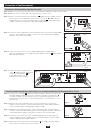
Варианты шнуров для PDUBHV10
(приобретаются отдельно)
Модель
Длина
Тип вилки
P005-002
0,6 м
C14
P005-006
1,8 м
C14
P005-010
3 м
C14
P011-006
1,8 м
L6-20P
P032-007
2,1 м
C20
P054-006
1,8 м
CEE 7/7
P056-006
1,8 м
BS1363
Варианты шнуров для PDUBHV20
(приобретаются отдельно)
Модель
Длина
Тип вилки
P036-006
1,8 м
C20
P036-002
0,6 м
C20
P040-010
3 м
L6-20P
P047-002
0,6 м
C14
P047-004
1,2 м
C14
P047-006
1,8 м
C14
P047-010
3 м
C14
P050-008
2,4 м
CEE 7/7
P052-008
2,4 м
BS1363