7
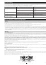
Troubleshooting
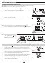
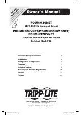
Use the following chart to make minor adjustments or attempt to solve problems. Do not attempt to open the PDU, as there are no user-serviceable
parts inside. If problems persist after troubleshooting, please visit www.tripplite.com/support.
Problem
Possible Cause
Possible Solution
Yellow light does not illuminate.
No utility power.
Contact your utility company or a qualified
electrician.
The PDU is not plugged into the utility source.
Connect the PDU to a compatible utility
source.
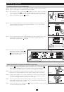
Green light does not illuminate.
The UPS system has no output.
Refer to the UPS manual for proper startup.
Input and output of UPS not connected to the PDU.
Connect UPS input and output to the PDU.
Some loads not receiving power.
Tripped circuit breaker on the PDU (PDUB30 only).
Reset the PDU’s circuit breaker.
Loads not receiving power after
resetting the circuit breaker.
The connected load is overloading the PDU.
Reduce the connected load.
Service, Warranty and Warranty Registration
Service
Your Tripp Lite product is covered by the warranty described in this manual. A variety of Extended Warranty and On-Site Service Programs are also available from Tripp Lite. For more
information on service, visit www.tripplite.com/support. Before returning your product for service, follow these steps:
1. Review the installation and operation procedures in this manual to insure that the service problem does not originate from a misreading of the instructions.
2. If the problem continues, do not contact or return the product to the dealer. Instead, visit www.tripplite.com/support.
3. If the problem requires service, visit www.tripplite.com/support and click the Product Returns link. From here you can request a Returned Material Authorization (RMA) number, which
is required for service. This simple on-line form will ask for your unit’s model and serial numbers, along with other general purchaser information. The RMA number, along with ship-
ping instructions will be emailed to you. Any damages (direct, indirect, special or consequential) to the product incurred during shipment to Tripp Lite or an authorized Tripp Lite service
center is not covered under warranty. Products shipped to Tripp Lite or an authorized Tripp Lite service center must have transportation charges prepaid. Mark the RMA number on the
outside of the package. If the product is within its warranty period, enclose a copy of your sales receipt. Return the product for service using an insured carrier to the address given to you
when you request the RMA.
Warranty
2-YEAR LIMITED WARRANTY
Seller warrants this product, if used in accordance with all applicable instructions, to be free from original defects in material and workmanship for a period of 2 years from the date of initial
purchase. If the product should prove defective in material or workmanship within that period, Seller will repair or replace the product, in its sole discretion. Service under this Warranty
can only be obtained by your delivering or shipping the product (with all shipping or delivery charges prepaid) to: Tripp Lite; 1111 W. 35th Street; Chicago IL 60609; USA. Seller will pay
return shipping charges. Visit www.tripplite.com/support before sending any equipment back for repair.
THIS WARRANTY DOES NOT APPLY TO NORMAL WEAR OR TO DAMAGE RESULTING FROM ACCIDENT, MISUSE, ABUSE OR NEGLECT. SELLER MAKES NO EXPRESS
WARRANTIES OTHER THAN THE WARRANTY EXPRESSLY SET FORTH HEREIN. EXCEPT TO THE EXTENT PROHIBITED BY APPLICABLE LAW, ALL IMPLIED WAR-
RANTIES, INCLUDING ALL WARRANTIES OF MERCHANTABILITY OR FITNESS, ARE LIMITED IN DURATION TO THE WARRANTY PERIOD SET FORTH ABOVE; AND
THIS WARRANTY EXPRESSLY EXCLUDES ALL INCIDENTAL AND CONSEQUENTIAL DAMAGES. (Some states do not allow limitations on how long an implied warranty lasts,
and some states do not allow the exclusion or limitation of incidental or consequential damages, so the above limitations or exclusions may not apply to you. This Warranty gives you spe-
cific legal rights, and you may have other rights which vary from jurisdiction to jurisdiction).
Tripp Lite; 1111 W. 35th Street; Chicago IL 60609; USA
WARNING: The individual user should take care to determine prior to use whether this device is suitable, adequate or safe for the use intended. Since individual applications are subject to
great variation, the manufacturer makes no representation or warranty as to the suitability or fitness of these devices for any specific application.
WARRANTY REGISTRATION
Visit www.tripplite.com/warranty today to register the warranty for your new Tripp Lite product. You’ll be automatically entered into a drawing for a chance to win a FREE Tripp Lite
product!*
* No purchase necessary. Void where prohibited. Some restrictions apply. See website for details.
WEEE Compliance Information for Tripp Lite Customers and Recyclers (European Union)
Under the Waste Electrical and Electronic Equipment (WEEE) Directive and implementing regulations, when customers buy new electrical and electronic equipment from Tripp Lite they
are entitled to:
Send old equipment for recycling on a one-for-one, like-for-like basis (this varies depending on the country)
•
Send the new equipment back for recycling when this ultimately becomes waste
•
Regulatory Compliance Identification Numbers
For the purpose of regulatory compliance certifications and identification, your Tripp Lite product has been assigned a unique series number. The series number can be found on the product
nameplate label, along with all required approval markings and information. When requesting compliance information for this product, always refer to the series number. The series number
should not be confused with the marking name or model number of the product.
Tripp Lite follows a policy of continuous improvement. Product specifications are subject to change without notice.
200908131 • 932933-EN
1111 W. 35th Street, Chicago, IL 60609 USA
www.tripplite.com/support