82
71.03982.03 - EN
INSTALLATION INSTRUCTIONS
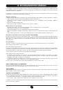
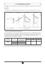
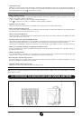
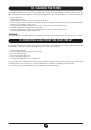
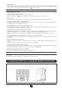
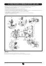
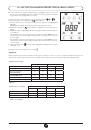
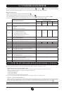
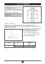
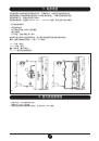
19. GAS CONVERSION
The authorised Technical Assistance Service can convert this boiler to natural gas (
G. 20
) or liquid gas (
G.31
).
Carry out the following operations:
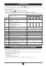
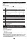
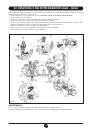
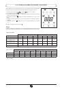
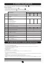
A) replace the nozzles of the main burner and the gas diaphragm (if itted);
B) new max. and min. calibration of the pressure regulator.
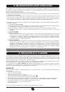
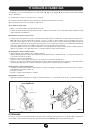
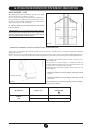
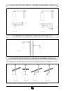
A) Replace the burner nozzles
• carefully pull the main burner off its seat;
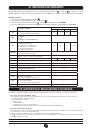
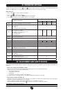
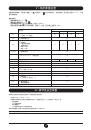
• replace the main burner nozzles making sure to fully tighten them to prevent gas leaks. Nozzle diameters are speciied
in table 2.
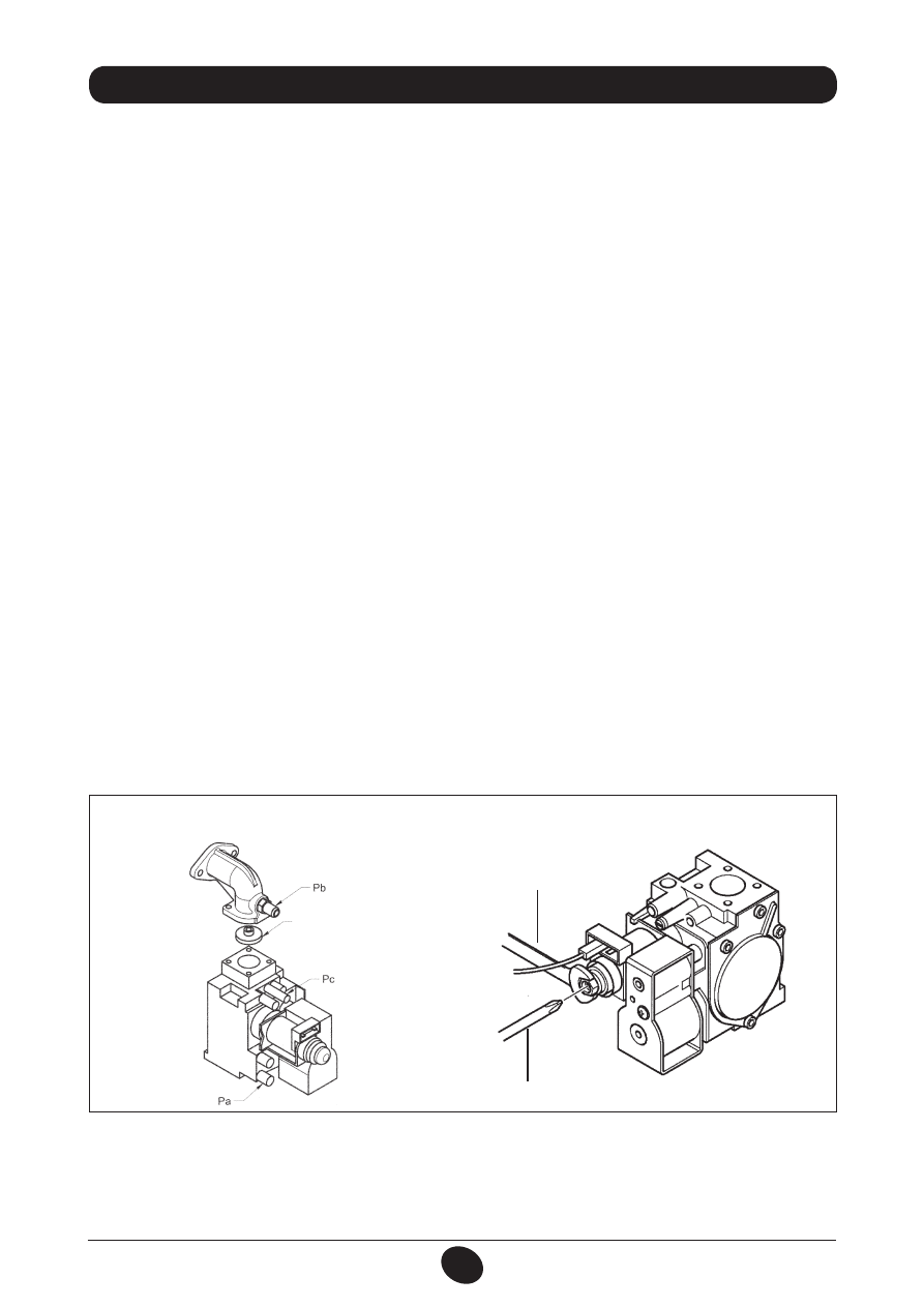
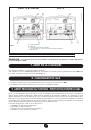
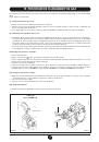
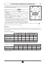
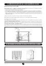
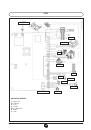
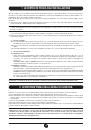
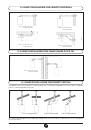
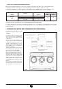
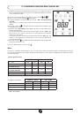
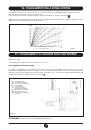
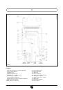
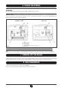
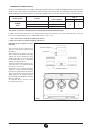
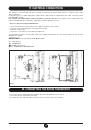
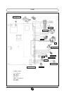
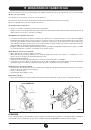
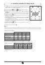
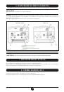
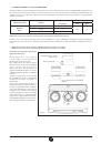
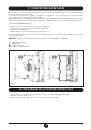
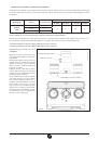
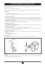
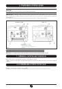
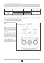
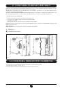
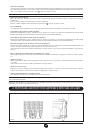
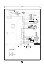
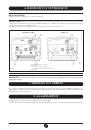
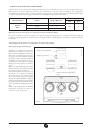
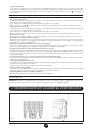
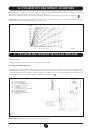
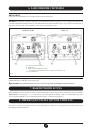
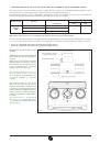
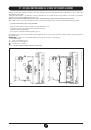
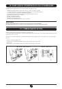
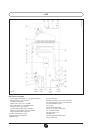
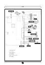
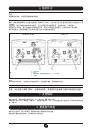
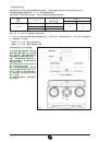
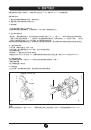
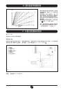
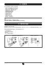
B) Calibrate the pressure regulator
• connect the positive pressure test point of a differential pressure gauge (possibly water-operated) to the gas valve
pressure test point (
Pb
) (Figure 10). Only for models with sealed chambers, connect the negative pressure test point of
the manometer to a “T” itting in order to join the boiler adjustment outlet, the gas valve adjusting outlet (Pc) and the
pressure gauge. (The same measurement can be made by connecting the pressure gauge to the pressure test point
(
Pb
) after removing the front panel of the sealed chamber);
Measuring burner pressure using methods other than those described could lead to incorrect results as the low pressure
created by the fan in the sealed chamber would not be taken into account.
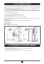
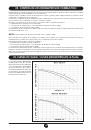
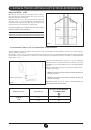
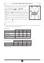
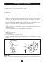
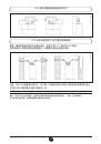
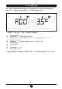
B1) Adjustment to nominal heat output:
• open the gas tap and switch the boiler to the Winter mode;
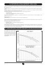
• open a hot water tap that can provide a low rate of at least 10 litres a minute or make sure there is maximum heat
demand;
• remove the modulator cover;
• adjust the tube brass screw (a) until the pressure values shown in table 1 are obtained;
make sure that the dynamic inlet pressure of the boiler, measured at the gas valve pressure test point (Pa) (Figure 10) is
correct (37 mbar for propane or 20 mbar for natural gas).
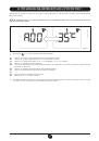
B2) Adjustment to reduced heat output:
• disconnect the modulator power cable and unscrew the screw (b) until a pressure value corresponding to reduced heat
output is achieved (see tab. 1);
• reconnect the cable;
• mount the modulator cover and seal.
B3) Final checks
• attach the additional plate supplied with the transformer, specifying the type of gas and the calibration performed.
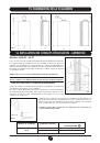
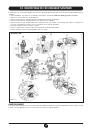
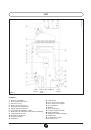
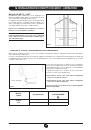
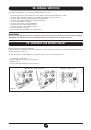
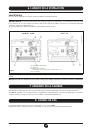
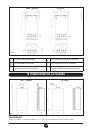
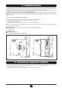
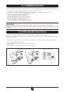
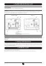
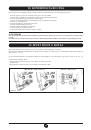
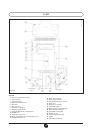
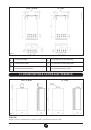
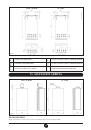
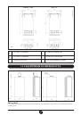
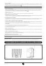
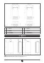
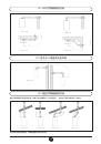
Figure 10
gas valve
mod. SIGMA 845
b
a
0605_1502
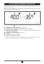
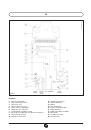
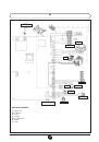
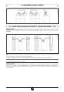
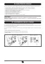
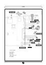
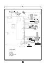
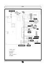
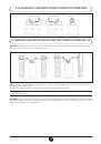
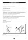
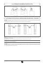
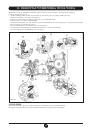
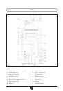
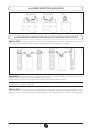
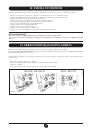
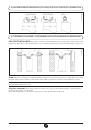
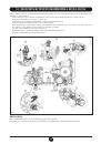
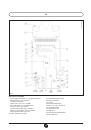
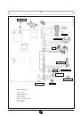
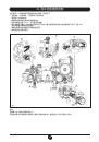
Figure 11
CG_2273 / 1008_2602
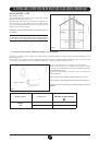
gas diaphragm
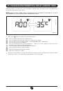
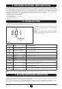
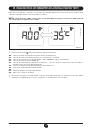
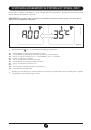
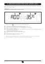
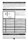
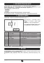
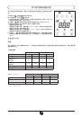
ATTENTION
If the natural gas inlet pressure is too low (less than 17 mbar) remove the gas diaphragm installed over the gas valve (ig.
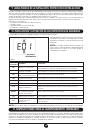
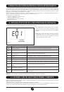
10) and set parameter
F02=00
on the electronic board (§21).
 1
1
 2
2
 3
3
 4
4
 5
5
 6
6
 7
7
 8
8
 9
9
 10
10
 11
11
 12
12
 13
13
 14
14
 15
15
 16
16
 17
17
 18
18
 19
19
 20
20
 21
21
 22
22
 23
23
 24
24
 25
25
 26
26
 27
27
 28
28
 29
29
 30
30
 31
31
 32
32
 33
33
 34
34
 35
35
 36
36
 37
37
 38
38
 39
39
 40
40
 41
41
 42
42
 43
43
 44
44
 45
45
 46
46
 47
47
 48
48
 49
49
 50
50
 51
51
 52
52
 53
53
 54
54
 55
55
 56
56
 57
57
 58
58
 59
59
 60
60
 61
61
 62
62
 63
63
 64
64
 65
65
 66
66
 67
67
 68
68
 69
69
 70
70
 71
71
 72
72
 73
73
 74
74
 75
75
 76
76
 77
77
 78
78
 79
79
 80
80
 81
81
 82
82
 83
83
 84
84
 85
85
 86
86
 87
87
 88
88
 89
89
 90
90
 91
91
 92
92
 93
93
 94
94
 95
95
 96
96
 97
97
 98
98
 99
99
 100
100
 101
101
 102
102
 103
103
 104
104
 105
105
 106
106
 107
107
 108
108
 109
109
 110
110
 111
111
 112
112
 113
113
 114
114
 115
115
 116
116
 117
117
 118
118
 119
119
 120
120
 121
121
 122
122
 123
123
 124
124
 125
125
 126
126
 127
127
 128
128
 129
129
 130
130
 131
131
 132
132
 133
133
 134
134
 135
135
 136
136
 137
137
 138
138
 139
139
 140
140
 141
141
 142
142
 143
143
 144
144
 145
145
 146
146
 147
147
 148
148
 149
149
 150
150
 151
151
 152
152
 153
153
 154
154
 155
155
 156
156
 157
157
 158
158
 159
159
 160
160
 161
161
 162
162
 163
163
 164
164
 165
165
 166
166
 167
167
 168
168
 169
169
 170
170
 171
171
 172
172
 173
173
 174
174
 175
175
 176
176
 177
177
 178
178
 179
179
 180
180
 181
181
 182
182
 183
183
 184
184
 185
185
 186
186
 187
187
 188
188
 189
189
 190
190
 191
191
 192
192
 193
193
 194
194
 195
195
 196
196
 197
197
 198
198
 199
199
 200
200
 201
201
 202
202
 203
203
 204
204
 205
205
 206
206
 207
207
 208
208
 209
209
 210
210
 211
211
 212
212
 213
213
 214
214
 215
215
 216
216
 217
217
 218
218
 219
219
 220
220
 221
221
 222
222
 223
223
 224
224
 225
225
 226
226
 227
227
 228
228
 229
229
 230
230
 231
231
 232
232
 233
233
 234
234
 235
235
 236
236
 237
237
 238
238
 239
239
 240
240
 241
241
 242
242
 243
243
 244
244
 245
245
 246
246
 247
247
 248
248
 249
249
 250
250
 251
251
 252
252
 253
253
 254
254
 255
255
 256
256
 257
257
 258
258
 259
259
 260
260
 261
261
 262
262
 263
263
 264
264
 265
265
 266
266
 267
267
 268
268
 269
269
 270
270
 271
271
 272
272
 273
273
 274
274
 275
275
 276
276
 277
277
 278
278
 279
279
 280
280
 281
281
 282
282
 283
283
 284
284
 285
285
 286
286
 287
287
 288
288
 289
289
 290
290
 291
291
 292
292
 293
293
 294
294
 295
295
 296
296
 297
297
 298
298
 299
299
 300
300
 301
301
 302
302
 303
303
 304
304
 305
305
 306
306
 307
307
 308
308
 309
309
 310
310
 311
311
 312
312
 313
313
 314
314
 315
315
 316
316
 317
317
 318
318
 319
319
 320
320
 321
321
 322
322
 323
323
 324
324
 325
325
 326
326
 327
327
 328
328
 329
329
 330
330
 331
331
 332
332