English
12
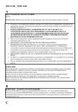
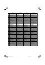
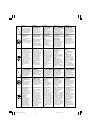
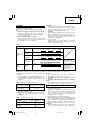
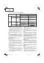
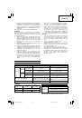
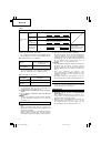
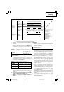
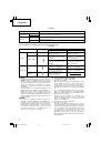
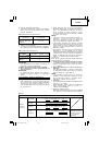
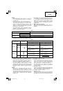
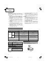
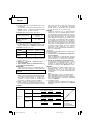
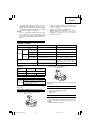
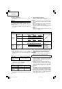
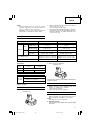
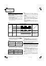
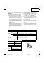
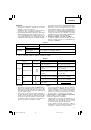
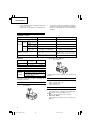
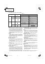
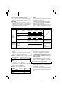
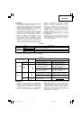
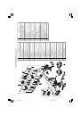
Work
Suggestions
Wood
Drilling
Steel
Use for drilling purpose.
Machine screw
Use the bit or socket matching the screw diameter.
Driving
Wood screw
Use after drilling a pilot hole.
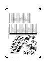
Table 7
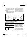
CAUTION
䡬
When the battery charger has been continuously
used, the battery charger will be heated, thus
constituting the cause of the failures. Once the
charging has been completed, give 15 minutes rest
until the next charging.
䡬
If the battery is recharged when it is warm due to
battery use or exposure to sunlight, the pilot lamp
map light in green.
The battery will not be recharged. In such a case,
let the battery cool before charging.
PRIOR TO OPERATION
1. Setting up and checking the work environment
Check if the work environment is suitable by
following the precautions.
HOW TO USE
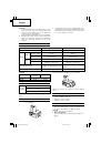
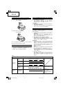
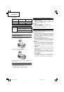
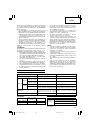
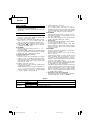
1. Confirm the clutch dial position (See Fig. 5)
The tightening torque of this unit can be adjusted
according to the clutch dial position, at which the
clutch dial is set.
(1) When using this unit as a screwdriver, line up the
one of the numbers “1, 3, 5 ... 22” on the clutch dial,
or the dots, with the triangle mark on the outer body.
(2) When using this unit as a drill, align the clutch dial
drill mark “
” with the triangle mark on the outer
body.
CAUTION
䡬
The clutch dial cannot be set between the numerals
“1, 3, 5 ... 22” or the dots.
䡬
Do not use with the clutch dial numeral between
“22” and the line at the middle of the drill mark.
Doing so may cause damage (See
Fig. 6
).
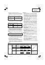
2. Tightening torque adjustment
(1) Tightening torque
Tightening torque should correspond in its intensity
to the screw diameter. When too strong torque is
used, the screw head may be broken or be injured.
Be sure to adjust the clutch dial position according
to the screw diameter.
(2) Tightening torque indication
The tightening torque differs depending on the type
of screw and the material being tightened.
The unit indicates the tightening torque with the
numbers “1, 3, 5 ... 22” on the clutch dial, and a
dots. The tightening toque at position “1” is the
weakest and the torque is strongest at the highest
number (See
Fig. 5
).
(3) Adjusting the tightening torque
Rotate the clutch dial and line up the numbers “1,
3, 5 ... 22” on the clutch dial, or the dots, with the
triangle mark on the outer body. Adjust the clutch
dial in the weak or the strong torque direction
according to the torque you need.
CAUTION
䡬
The motor rotation may be locked to cease while
the unit is used as drill. While operating the driver
drill, take care not to lock the motor.
䡬
Too long hammering may cause the screw broken
due to excessive tightening.
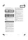
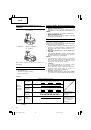
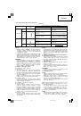
3. Change rotation speed
Operate the shift knob to change the rotational
speed. Move the shift knob in the direction of the
arrow (See
Figs. 7
and
8
).
When the shift knob is set to “LOW”, the drill
rotates at a low speed. When set to “HIGH”, the
drill rotates at a high speed.
CAUTION
䡬
When changing the rotational speed with the shift
knob, confirm that the switch is off.
Changing the speed while the motor is rotating will
damage the gears.
䡬
When setting the shift knob to “HIGH” (high speed)
and the position of the clutch dial is “17” or “22”,
it may happen that the clutch does not engaged
and that the motor is locked. In such a case, please
set the shift knob to “LOW” (low speed).
䡬
If the motor is locked, immediately turn the power
off. If the motor is locked for a while, the motor
or battery may be burnt.
䡬
To extend the lifetime, the lithium-ion battery equips
with the protection function to stop the output.
Therefore, if the tool is overloaded, the motor may
stop. However, this is not the trouble but the result
of protection function. In this case, release the switch
of tool and eliminate the causes of overloading.
4. The scope and suggestions for uses
The usable scope for various types of work based
on the mechanical structure of this unit is shown
in
Table 7
.
01Eng_DS14DFL_EE
4/30/10, 15:24
12
 1
1
 2
2
 3
3
 4
4
 5
5
 6
6
 7
7
 8
8
 9
9
 10
10
 11
11
 12
12
 13
13
 14
14
 15
15
 16
16
 17
17
 18
18
 19
19
 20
20
 21
21
 22
22
 23
23
 24
24
 25
25
 26
26
 27
27
 28
28
 29
29
 30
30
 31
31
 32
32
 33
33
 34
34
 35
35
 36
36
 37
37
 38
38
 39
39
 40
40
 41
41
 42
42
 43
43
 44
44
 45
45
 46
46
 47
47
 48
48
 49
49
 50
50
 51
51
 52
52
 53
53
 54
54
 55
55
 56
56
 57
57
 58
58
 59
59
 60
60
 61
61
 62
62
 63
63
 64
64
 65
65
 66
66
 67
67
 68
68
 69
69
 70
70
 71
71
 72
72
 73
73
 74
74
 75
75
 76
76
 77
77
 78
78
 79
79
 80
80
 81
81
 82
82
 83
83
 84
84
 85
85
 86
86
 87
87
 88
88
 89
89
 90
90
 91
91
 92
92
 93
93
 94
94
 95
95
 96
96
 97
97
 98
98
 99
99
 100
100
 101
101
 102
102
 103
103
 104
104
 105
105
 106
106