English
14
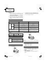
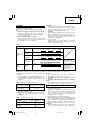
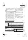
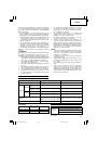
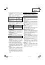
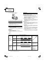
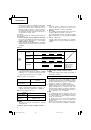
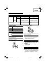
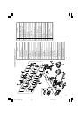
The hook can be installed on the right or left side and
the angle can be adjusted in 5 steps between 0° and
80°.
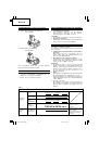
(1) Operating the hook
(a) Pull out the hook toward you in the direction
of arrow (A) and turn in the direction of arrow
(B) (
Fig. 12
).
(b) The angle can be adjusted in 5 steps (0°, 20°,
40°, 60°, 80°).
Adjust the angle of the hook to the desired
position for use.
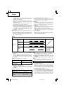
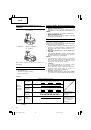
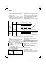
(2) Switching the hook position
CAUTION
Incomplete installation of the hook may result in
bodily injury when used.
(a) Securely hold the main unit and remove the
screw using a slotted head screwdriver or a coin
(
Fig. 13
).
(b) Remove the hook and spring (
Fig. 14
).
(c) Install the hook and spring on the other side and
securely fasten with screw (
Fig. 15
).
NOTE
Pay attention to the spring orientation. Install the
spring with larger diameter away from you (
Fig. 15
).
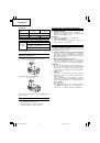
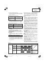
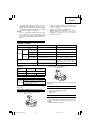
(3) Using the bit holder (Hook with bit holder)
䡬
Installing the bit
Slide the bit from the side and then insert firmly
until the groove on the bit locks in the protruded
section of the hook.
䡬
Removing the bit
Securely hold the main unit and pull out the bit
by holding the tip with your thumb (
Fig. 16
).
CAUTION
䡬
Only Hitachi STANDARD ACCESSORIES phillips bit
(No. 2
×
65L; Code No. 983006) may be used. Do
not use other bits since they may come loose.
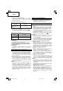
11. Using the bit holder
CAUTION
䡬
Stow the bit in the specified location on the tool.
If the tool is used with the bit stowed improperly,
the bit may fall and cause bodily injury.
䡬
Do not stow bits that are of a different length,
gauge or dimension than the plus driver bit (65 mm
long) included in the STANDARD ACCESSORIES.
The bit may fall and cause bodily injury.
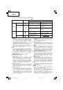
(1) Removing the bit
Securely hold the main unit and pull out the bit
by holding the tip with your thumb (
Fig. 17
).
(2) Installing the Bit
Install the bit with steps opposite of when removing.
Insert the bit so that the right and left sides are
equal, as shown in
Fig. 18
.
MAINTENANCE AND INSPECTION
1. Inspecting the tool
Since use of as dull tool will degrade efficiency and
cause possible motor malfunction, sharpen or
replace the tool as soon as abrasion is noted.
2. Inspecting the mounting screws
Regularly inspect all mounting screws and ensure
that they are properly tightened. Should any of the
screws be loose, retighten them immediately. Failure
to do so could result in serious hazard.
3. Cleaning on the outside
When the driver drill is stained, wipe with a soft
dry cloth or a cloth moistened with soapy water.
Do not use chloric solvents, gasoline or paint thinner,
for they melt plastics.
4. Storage
Store the driver drill in a place in which the temperature
is less than 40°C and out of reach of children.
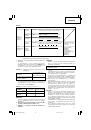
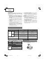
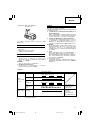
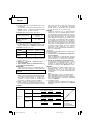
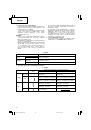
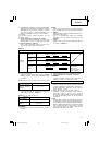
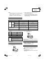
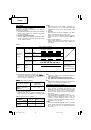
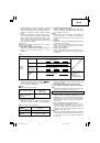
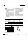
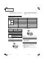
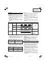
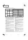
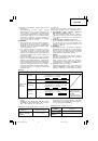
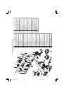
5. Service parts list
CAUTION
Repair, modification and inspection of Hitachi Power
Tools must be carried out by a Hitachi Authorized
Service Center.
This Parts List will be helpful if presented with the
tool to the Hitachi Authorized Service Center when
requesting repair or other maintenance.
In the operation and maintenance of power tools,
the safety regulations and standards prescribed in
each country must be observed.
MODIFICATIONS
Hitachi Power Tools are constantly being improved
and modified to incorporate the latest technological
advancements.
Accordingly, some parts may be changed without
prior notice.
GUARANTEE
We guarantee Hitachi Power Tools in accordance with
statutory/country specific regulation. This guarantee
does not cover defects or damage due to misuse,
abuse, or normal wear and tear. In case of complaint,
please send the Power Tool, undismantled, with the
GUARANTEE CERTIFICATE found at the end of this
Handling instruction, to a Hitachi Authorized Service
Center.
NOTE
Due to HITACHI’s continuing program of research and
development, the specifications herein are subject to
change without prior notice.
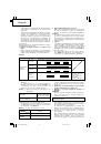
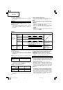
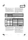
Information concerning airborne noise and vibration
The measured values were determined according to
EN60745 and declared in accordance with ISO 4871.
Measured A-weighted sound power level: 79 dB (A)
Measured A-weighted sound pressure level: 68 dB (A)
Uncertainty KpA: 3 dB (A).
Wear ear protection.
Vibration total values (triax vector sum) determined
according to EN60745.
Drilling:
Vibration emission value
a
h
,
D
= 1.5 m/s
2
Uncertainty K = 1.5 m/s
2
01Eng_DS14DFL_EE
4/30/10, 15:24
14
 1
1
 2
2
 3
3
 4
4
 5
5
 6
6
 7
7
 8
8
 9
9
 10
10
 11
11
 12
12
 13
13
 14
14
 15
15
 16
16
 17
17
 18
18
 19
19
 20
20
 21
21
 22
22
 23
23
 24
24
 25
25
 26
26
 27
27
 28
28
 29
29
 30
30
 31
31
 32
32
 33
33
 34
34
 35
35
 36
36
 37
37
 38
38
 39
39
 40
40
 41
41
 42
42
 43
43
 44
44
 45
45
 46
46
 47
47
 48
48
 49
49
 50
50
 51
51
 52
52
 53
53
 54
54
 55
55
 56
56
 57
57
 58
58
 59
59
 60
60
 61
61
 62
62
 63
63
 64
64
 65
65
 66
66
 67
67
 68
68
 69
69
 70
70
 71
71
 72
72
 73
73
 74
74
 75
75
 76
76
 77
77
 78
78
 79
79
 80
80
 81
81
 82
82
 83
83
 84
84
 85
85
 86
86
 87
87
 88
88
 89
89
 90
90
 91
91
 92
92
 93
93
 94
94
 95
95
 96
96
 97
97
 98
98
 99
99
 100
100
 101
101
 102
102
 103
103
 104
104
 105
105
 106
106