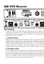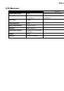
XD-V70 Receiver
2•3
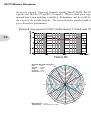
RF
These LEDs indicate Radio Frequency signal strength. When all five LEDs are lit green
the receiver is receiving full signal. As signal strength is diminished, LEDs will begin to
turn off. If you experience fewer than all five LEDs, one or more of the following steps
should be attempted:
• Antenna placement should be moved closer to transmitter
• Move transmitter closer to receiver
• Provide a clearer line of sight between transmitter and receiver
• Place transmitter into high power mode
• Utilize external antennas when receiver and transmitter positioning cannot be
improved
When no transmitter is turned on, these LEDs may light red indicating that there is some
non-Line 6 RF in the area. This is usually not a concern. When an XD-V transmitter
is turned on the receiver will lock to it and disregard the RF noise because of DCL™
technology.
Antenna Management
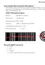
1. External Antennas
The XD-V70 system must be operated with external antennas. The supplied “rubber
duckie” antennas should be connected to the BNC connectors marked “Antenna A”
and “Antenna B” before operating. The user may wish to front mount the antennas by
installing the supplied BNC bulkhead connectors in the long rack ear when installing in
a rack. Connect the supplied antenna cables from the BNC terminals to the “Antenna
A” and “Antenna B” connectors on the rear panel. Optional Line 6 P180 or P360 paddle
antennas may be used in place of the standard “rubber ducky” antennas for increased
performance or when the receiver cannot be physically placed in a location within range
of the transmitter. See the Paddle antenna owner’s manuals for details.
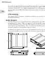
2. Looping – Antenna Distribution System
If you are operating more than one system you may conveniently connect multiple receivers
to a single pair of antennas using XD-V70’s built-in antenna distribution system. After
attaching antennas to the primary receiver, simply use the supplied cables and connect
from the BNC connector marked “A Out” to the “Antenna A” input of the second unit.
Similarly, connect from the “B Out” on the primary unit to the “Antenna B” input on the
second receiver. You may continue this process connecting up to 12 systems total. For