24
25
English
RSX-1560 Surround Sound Receiver
24
25
English
RSX-1560 Surround Sound Receiver
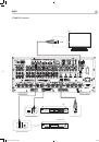
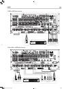
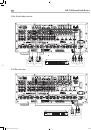
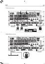
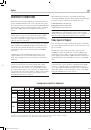
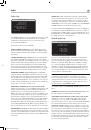
Amplifiers
f
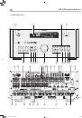
To hook up optional power amplifiers,
connect an audio cable
from each PREOUT jack to the input of the amplifier channel that will
power the corresponding speaker. In a full home theater system, you will
need to make as many as seven different connections in addition to the
subwoofer. These connections are labeled FRONT L &R, CENTER, and
REAR L & R. There are two CENTER jacks, use either jack for a single
center channel or both if you have two center channels. In six or seven
channel systems, you will make one or two additional connections for
center back speaker(s). These jacks are labeled CB1 and CB2. Use CB1
for a single center back channel.
Make sure that you have each output connected to the correct amplifier
channel (front right, left rear, etc.).
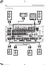
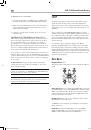
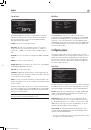
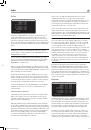
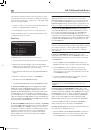
AM Antenna
u
See Figure 12
The receiver includes a plastic loop antenna to receive AM radio signals.
Remove this antenna from the box and locate it near the receiver. It can
be tacked to a wall, using the mounting tab provided. Alternatively, you
can fold the center portion of the antenna to form a tabletop stand.
Connect the 300 ohm twin-conductor wire from the loop antenna to the
push terminals labeled AM LOOP, attaching one wire to each terminal.
It does not matter which wire attaches to which terminal, but make sure
that the connections are solid and that the two wires do not touch.
You may need to rotate or otherwise reorient the antenna to find the best
position.
Note:
To use an outdoor antenna, connect its 300 ohm twin-
conductor wire to the terminals in place of the loop antenna.
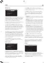
FM Antenna
y
See Figure 12
The receiver is supplied with a T-shaped indoor FM antenna. Connect the
coax F-type plug to the FM antenna connector on the RSX-1560. For best
reception, unfold the T-shaped antenna. Eyelets at both ends of the T allow
tacking the antenna to a wall, if desired. Experiment with positioning for
best reception.
Note:
To use an outdoor antenna, connect its 75 ohm coax lead
wire to the FM connector instead of the indoor wire antenna, only
after a professional contractor has installed the antenna system in
accordance with local electrical codes.
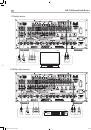
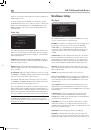
Remote Zone Connections
sjk
This Rotel receiver has connections for three independent remote zones.
For audio connections to a remote zone
, connect the left and right
ZONE 2, 3, or 4 jacks to the left and right channels of a remote zone
amplifier with an RCA audio cable.
For video connections to a remote zone,
connect the ZONE 2, 3,
or 4 VIDEO OUT jack to the input of a TV in the remote zone using a
Composite Video or S-Video cable.
For control of the receiver from a remote zone:
connect a remote
zone IR repeater to the ZONE 2, ZONE 3, or ZONE 4 REM IN jack
using a cable terminated with 3.5mm plugs.
Class D amplification
This Rotel receiver uses an advanced form of Class D amplification,
which has many advantages over conventional Class AB amplifiers,
particularly where high power output is needed.
With this technology, amplifiers can be made many times smaller and
lighter. Up to five times less electrical power is needed from the AC
household wall socket to produce a given amount of sound power from
the speakers.
This is because Class D amplifiers are inherently very much more
efficient. When a conventional amplifier is running, it converts some
of the energy from the AC power into sound, but most of the power is
converted into heat and wasted. By contrast, a Class D amplifier can
convert at least 90% of the power it receives from the AC socket into
sound.
It’s sometimes wrongly thought that the ‘D’ in ‘Class D’ stands for digital.
This can lead to a misconception that Class D amplifiers are not analog
in their audio output stages. In fact, the operation of a Class D amplifier
is based on analog principles.
More correctly, Class D amplifiers can be described as ‘switching
amplifiers’, because the transistors switch on and off many thousands of
times per second. There is no digital coding of the audio signal, although
it is treated as a series of pulses within the amplifier, before appearing as
pure analog power at the output.
The switching frequency itself is many times higher than the highest
audio frequency and does not in any way affect the analog audio output
of the amplifier, as it is completely removed by filtering.
In a conventional amplifier, the power transistors or other devices are
driven linearly and are ‘on’ all the time, demanding current from the
supply and dissipating heat continuously. In Class D, since the transistors
are only turned on and off, their power requirement is much less.
With so much less energy being wasted as heat, Class D amplifiers do
not need the large mains transformers and big reservoir capacitors
used in conventional amplifiers, nor do they need large heatsink fins or
internal fans.
Also, the actual usable output power of a Class D amplifier is typically
much greater than the conventional measurement rating. Typically, a
100 watt Class D amplifier can deliver more than 200 watts into a 4
ohm load and close to 300 watts into 2 ohms, while also giving lower
background noise and more accurate sound.
RSX-1560 English v2.indd 25
29/9/08 15:15:59