22
23
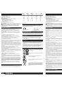
WS 12
WSC 14
WSE 14
PE 150
SE 12
-125 MX
-125 MX
-125 MX
-180
.......... 1200 ................. 1450 ................. 1450 ................. 1200 ................. 1200
........... 720 ................... 870 ................... 870 ................... 600 ................... 600
..........11000 ................11000 ...........2600-11000 ........900-2500 .........1800-4800
..............- ........................- ........................- .................... 4700 ................. 9000
........... 125 ................... 125 ................... 125 ................... 150 ................... 180
.......... M 14 ................. M 14 ................. M 14 ................. M 14 ................. M 14
............2,5 ....................2,5 ....................2,5 ....................2,1 ....................2,5
............7,0 ....................4,5 ....................4,5 .................. < 2,5 ................. < 2,5
............ 89 ..................... 89 ..................... 89 ..................... 82 ..................... 82
........... 100 ................... 100 ................... 100 .................... 93 ..................... 93
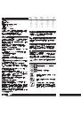
ENGLISH
TECHNICAL DATA
Rated input (W) .................................................................................................
Output (W) .........................................................................................................
No-load speed (min
-1
)........................................................................................
Max. no-load speed (min
-1
) ................................................................................
Grinding disk diameter (mm) .............................................................................
Thread of work spindle ......................................................................................
Weight without cable (kg) ..................................................................................
Typical weighted acceleration in the hand-arm area (m/s
2
) ...............................
Typical A-weighted sound levels:
Sound pressure level (dB (A)) (K = 3 dB(A)) ...................................................
Sound power level (dB (A)) (K = 3 dB(A)) .......................................................
Wear ear protectors!
Measured values determined according to EN 50144.
WARNING! Read all safety warnings and all instructions, including
those given in the accompanying brochure
. Failure to follow the warnings
and instructions may result in electric shock, fire and/or serious injury.
Save all warnings and instructions for future reference.
SAFETY INSTRUCTIONS
Wear ear protectors.
Exposure to noise can cause hearing loss.
Use auxiliary handles supplied with the tool.
Loss of control can cause
personal injury.Appliances used at many different locations including open
air must be connected via a current surge preventing switch.
Hold power tool by insulated gripping surfaces, when performing an
operation where the cutting accessory may contact hidden wiring or its
own cord.
Contact with a „live“ wire will also make exposed metal parts of
the power tool „live“ and shock the operator.
Appliances used at many different locations including open air should be
connected via a residual current device of 30 mA or less.
Always wear goggles when using the machine. It is recommended to wear
gloves, sturdy non slipping shoes and apron.
Sawdust and splinters must not be removed while the machine is running.
Always disconnect the plug from the socket before carrying out any work on
the machine.
Only plug-in when machine is switched off.
Keep mains lead clear from working range of the machine. Always lead the
cable away behind you.
After switching off, the machine will not be idle immediately. (After-running of
the work spindle.) Allow the machine to come to a stop before putting down.
Never reach into the danger area of the plane when it is running.
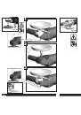
Always use the auxiliary handle.
Always use the protecting cap when roughing-down and separating.
Only use tools whose permitted speed is at least as high as the highest
no-load speed of the machine.
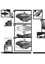
Pay attention to the dimensions of the grinding disc. The mounting hole
diameter must fit the mounting flange without play. Do not use reducer
pieces or adapters.
Check grinding tools before use. The grinding tool must be properly mounted
and turn freely. Perform a test run for at least 30 seconds without load. Do
not use damaged, out of round or vibrating grinding tools.
Immediately switch off the machine in case of considerable vibrations or if
other malfunctions occur. Check the machine in order to find out the cause.
Always use and store the grinding disks according to the manufacturer's
instructions.
When grinding metal, flying sparks are produced. Take care that no persons
are endangered. Because of the danger of fire, no combustible materials
should be located in the vicinity (spark flight zone). Do not use dust
extraction.
Due care should be taken that no sparks or sanding dust flying from the
workpiece come into contact with you.
Never use a cutting disc for grinding. Do not subject cutting discs to side
pressure.
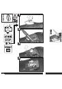
The adjusting nut must be tightened before starting to work with the
machine.
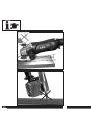
The workpiece must be fixed if it is not heavy enough to be steady. Never
lead the workpiece to the grinding disk with your hand.
Under extreme conditions (e.g. smooth-grinding metals with the arbour and
vulcanized fibre grinding wheel), significant contamination can build up on
the inside of the angle grinder. For safety reasons, in such conditions the
inside should be cleaned thoroughly of metal deposits and a motor
circuit-breaker must be connected in series. If the motor circuit-breaker trips
the machine must be sent for repair.
For tools intended to be fitted with threaded hole wheel, ensure that the
thread in the wheel is long enough to accept the spindle length.
SPECIFIED CONDITIONS OF USE
This angle grinder can be used for separating and grinding many different
materials, e.g. metal or stone. In case of doubt please read the
manufacturers' instruction.
Do not use this product in any other way as stated for normal use.
EC-DECLARATION OF CONFORMITY
We declare under our sole responsibility that this product is in conformity
with the following standards or standardized documents. EN 50144, EN
55014-1, EN 55014-2, EN 61000-3-2, EN 61000-3-3, in accordance with the
regulations 98/37/EC, 2004/108/EC
Rainer Kumpf
Manager Product Development
Winnenden, 2009-03-07
MAINS CONNECTION
Connect only to single-phase a.c. current and only to the system voltage
indicated on the rating plate. It is also possible to connect to sockets without
an earthing contact as the design conforms to safety class II.
ELECTRONICS
The speed of rotation is adjusted electronically when the load increases.
In case of a longer overload period the speed is decreased electronically.
The machine continues to run slowly to cool down the motor coil. After
switching off and on the machine can be used at rated load.
MAINTENANCE
The ventilation slots of the machine must be kept clear at all times.
Use only Milwaukee accessories and Milwaukee spare parts. Should
components need to be replaced which have not been described, please
contact one of our Milwaukee service agents (see our list of guarantee/
service addresses).
If needed, an exploded view of the tool can be ordered. Please state the
ten-digit No. as well as the machine type printed on the label and order the
drawing at your local service agents or directly at: Milwaukee Electric Tool,
Max-Eyth-Straße 10, D-71364 Winnenden, Germany.
SYMBOLS
Please read the instructions carefully before starting
the machine.
Always wear goggles when using the machine.
Always disconnect the plug from the socket before
carrying out any work on the machine.
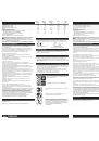
Accessory - Not included in standard equipment,
available as an accessory.
Do not dispose of electric tools together with household
waste material! In observance of European Directive
2002/96/EC on waste electrical and electronic
equipment and its implementation in accordance with
national law, electric tools that have reached the end of
their life must be collected separately and returned to
an environmentally compatible recycling facility.
DEUTSCH
TECHNISCHE DATEN
Nennaufnahmeleistung (W) ...............................................................................
Abgabeleistung (W) ...........................................................................................
Leerlaufdrehzahl (min
-1
) .....................................................................................
max. Leerlaufdrehzahl (min
-1
) ............................................................................
max. Schleifscheiben-Ø (mm) ...........................................................................
Spindelgewinde .................................................................................................
Gewicht ohne Netzkabel (kg) ............................................................................
Typisch bewertete Beschleunigung im Hand-Arm-Bereich (m/s
2
) .....................
Typische A-bewertete Schallpegel:
Schalldruckpegel (dB (A)) (K = 3 dB(A)) .........................................................
Schalleistungspegel (dB (A)) (K = 3 dB(A)) .....................................................
Gehörschutz tragen!
Messwerte ermittelt entsprechend EN 50144.
WARNUNG!
Lesen Sie alle Sicherheitshinweise und Anweisungen,
auch die in der beiliegenden Broschüre.
Versäumnisse bei der Einhaltung
der Sicherheitshinweise und Anweisungen können elektrischen Schlag,
Brand und/oder schwere Verletzungen verursachen.
Bewahren Sie alle Sicherheitshinweise und Anweisungen für die
Zukunft auf.
SPEZIELLE SICHERHEITSHINWEISE
Tragen Sie Gehörschutz.
Die Einwirkung von Lärm kann Gehörverlust
bewirken.
Benutzen Sie die mit dem Gerät gelieferten Zusatzhandgriffe.
Der
Verlust der Kontrolle kann zu Verletzungen führen.
Halten Sie das Gerät an den isolierten Griffflächen, wenn Sie Arbeiten
ausführen, bei denen das Einsatzwerkzeug verborgene Stromleitungen
oder das eigene Kabel treffen kann.
Der Kontakt mit einer
spannungsführenden Leitung setzt auch die metallenen Geräteteile unter
Spannung und führt zu einem elektrischen Schlag.
Steckdosen in Außenbereichen müssen mit Fehlerstrom-Schutzschaltern
ausgerüstet sein. Das verlangt die Installationsvorschrift für Ihre
Elektroanlage. Bitte beachten Sie das bei der Verwendung unseres Gerätes.
Beim Arbeiten mit der Maschine stets Schutzbrille tragen.
Schutzhandschuhe, festes und rutschsicheres Schuhwerk und Schürze
werden empfohlen.
Späne oder Splitter dürfen bei laufender Maschine nicht entfernt werden.
Vor allen Arbeiten an der Maschine Stecker aus der Steckdose ziehen.
Maschine nur ausgeschaltet an die Steckdose anschließen.
Anschlußkabel stets vom Wirkungsbereich der Maschine fernhalten. Kabel
immer nach hinten von der Maschine wegführen.
Die Werkzeugspindel läuft nach, nachdem das Gerät ausgeschaltet wurde.
Maschine erst nach Stillstand ablegen.
Nicht in den Gefahrenbereich der laufenden Maschine greifen.
Stets den Zusatzhandgriff verwenden.
Beim Schruppen und Trennen immer mit Schutzhaube arbeiten.
Nur Arbeitswerkzeuge verwenden, deren zulässige Drehzahl mindestens so
hoch ist wie die höchste Leerlaufdrehzahl des Gerätes.
Abmessungen der Schleifscheiben beachten. Lochdurchmesser muss ohne
Spiel zum Aufnahmeflansch passen. Keine Reduzierstücke oder Adapter
verwenden.
Schleifwerkzeuge vor dem Gebrauch überprüfen. Das Schleifwerkzeug
muss einwandfrei montiert sein und sich frei drehen können. Probelauf
mindestens 30 Sekunden ohne Belastung durchführen. Beschädigte,
unrunde oder vibrierende Schleifwerkzeuge nicht verwenden
Gerät sofort ausschalten, wenn beträchtliche Schwingungen auftreten oder
andere Mängel festgestellt werden. Überprüfen Sie die Maschine, um die
Ursache festzustellen.
Schleifscheiben stets gemäß den Angaben des Herstellers verwenden und
aufbewahren.
Beim Schleifen von Metallen entsteht Funkenflug. Darauf achten, dass keine
Personen gefährdet werden. Wegen der Brandgefahr dürfen sich keine
brennbaren Materialien in der Nähe (Funkenflugbereich) befinden. Keine
Staubabsaugung verwenden.
Gerät immer so halten, dass Funken oder Schleifstaub vom Körper
wegfliegen.
Niemals Trennscheiben zum Schruppschleifen verwenden. Trennscheiben
keinem seitlichen Druck aussetzen.
Die Spannmutter muss vor Inbetriebnahme der Maschine angezogen sein.
Das zu bearbeitende Werkstück muss festgespannt werden, sofern es nicht
durch sein Eigengewicht hält. Niemals Werkstück mit der Hand gegen die
Scheibe führen.
Bei extremen Einsatzbedingungen (z. B. beim Glattschleifen von Metallen
mit dem Stützteller und Vulkanfieber-Schleifscheiben) kann sich eine starke
Verschmutzung im Inneren des Winkelschleifers aufbauen. Bei solchen
Einsatzbedingungen ist aus Sicherheitsgründen eine gründliche Reinigung
im Inneren von Metallablagerungen und zwingend das Vorschalten eines
Fehlerstrom- (FI) Schutzschalters erforderlich. Nach Ansprechen des FI
Schutzschalters muss die Maschine zur Reparatur eingesandt werden.
Vergewissern Sie sich bei Schleifwerkzeugen mit Gewindeeinsatz, dass das
Gewinde lang genug ist, um die Spindellänge aufzunehmen.
BESTIMMUNGSGEMÄßE VERWENDUNG
Der Winkelschleifer ist einsetzbar zum Trennen und Schleifen von vielen
Materialien, wie z. B. Metall oder Stein. Beachten Sie im Zweifelsfall die
Hinweise der Schleifwerkzeughersteller.
Dieses Gerät darf nur wie angegeben bestimmungsgemäß verwendet
werden.
CE-KONFORMITÄTSERKLÄRUNG
Wir erklären in alleiniger Verantwortung, dass dieses Produkt mit den
folgenden Normen oder normativen Dokumenten übereinstimmt. EN 50144,
EN 55014-1, EN 55014-2, EN 61000-3-2, EN 61000-3-3, gemäß den
Bestimmungen der Richtlinien 98/37/EG, 2004/108/EG
Rainer Kumpf
Manager Product Development
Winnenden, 2009-03-07
NETZANSCHLUSS
Nur an Einphasen-Wechselstrom und nur an die auf dem Leistungsschild
angegebene Netzspannung anschließen. Anschluss ist auch an Steckdosen
ohne Schutzkontakt möglich, da ein Aufbau der Schutzklasse II vorliegt.
ELEKTRONIK
Die Elektronik regelt die Drehzahl bei steigender Belastung nach.
Bei längerer Überlastung schaltet die Elektronik auf reduzierte Drehzahl. Die
Maschine läuft langsam weiter zum Kühlen der Motorwicklung. Nach Aus-
und Wiedereinschalten kann mit der Maschine im Nennlastbereich
weitergearbeitet werden.
WARTUNG
Stets die Lüftungsschlitze der Maschine sauber halten.
Nur Milwaukee Zubehör und Milwaukee Ersatzteile verwenden. Bauteile,
deren Austausch nicht beschrieben wurde, bei einer Milwaukee
Kundendienststelle auswechseln lassen (Broschüre Garantie/
Kundendienstadressen beachten).
Bei Bedarf kann eine Explosionszeichnung des Gerätes unter Angabe der
Maschinen Type und der zehnstelligen Nummer auf dem Leistungsschild bei
Ihrer Kundendienststelle oder direkt bei Milwaukee Electric Tool,
Max-Eyth-Straße 10, D-71364 Winnenden, Germany angefordert werden.
SYMBOLE
Bitte lesen Sie die Gebrauchsanweisung vor
Inbetriebnahme sorgfältig durch.
Beim Arbeiten mit der Maschine stets Schutzbrille
tragen.
Vor allen Arbeiten an der Maschine Stecker aus der
Steckdose ziehen.
Zubehör - Im Lieferumfang nicht enthalten, empfohlene
Ergänzung aus dem Zubehörprogramm.
Werfen Sie Elektrowerkzeuge nicht in den Hausmüll!
Gemäss Europäischer Richtlinie 2002/96/EG über
Elektro- und Elektronik- Altgeräte und Umsetzung in
nationales Recht müssen verbrauchte
Elektrowerkzeuge getrennt gesammelt und einer
umweltgerechten Wiederverwertung zugeführt werden.