ITALIANO
GUIDA ALL’USO:
La saldatrice gestisce automaticamente una serie
di parametri che permettono il buon esito della saldatura:
HOT START (facilità di innesco dell’arco):
Nella fase iniziale, in
genere, la saldatura è resa difficoltosa dal fatto che l’elettrodo ed il
punto di attacco sono freddi. L’apparecchiatura fornisce in questa
fase una corrente di innesco più elevata per un tempo limitato
rispetto al valore impostato. Questo agevola l’accensione e la
stabilità dell’arco.
ARC FORCE (modulazione della corrente di saldatura):
Durante
la saldatura l’elettrodo è guidato dalla mano dell’operatore per cui
varia la sua distanza dal piano di saldatura. Per evitare che
l’elettrodo avvicinandosi troppo velocemente alla parte in fusione si
incolli l’apparecchiatura fornisce una corrente più elevata rispetto a
quella impostata per far cessare velocemente il corto circuito.
ANTI STICK (rimozione del corto circuito):
Se durante la saldatura
si genera un corto circuito permanente si attiva la funzione di Anti
Stick che riduce la corrente di saldatura ad un valore tale da
permettere di rimuovere l’elettrodo dalla condizione di corto circuito
nel bagno fuso e riprendere la normale condizione di esercizio.
PROTEZIONE TERMICA:
quando l’indicatore giallo è acceso non è
possibile effettuare la saldatura. L’indicatore si spegne
automaticamente quando l’apparecchio si raffredda e indica che è
possibile ritornare a saldare. All’accensione dell’apparecchio
l’indicatore si accende per circa tre secondi e indica che è in corso il
check dell’elettronica, durante questo tempo non è possibile
effettuare la saldatura.
NO STOP:
Selezionando attraverso l’interruttore la funzione NO
STOP si attiva un circuito di regolazione ausiliaria e si disattiva la
manopola di regolazione; è garantita una maggiore continuità di
saldatura e le migliori caratteristiche d’arco. Selezionando la funzione
“Basic MMA” mediante l’interruttore si disattiva la funzione NO STOP
ed è possibile impostare i parametri appropriati per ogni tipo di
elettrodo.
TIG:
Permette di selezionare il procedimento di saldatura desiderato:
•
Posizione MMA per saldare con elettrodo.
•
Posizione TIG per saldare in TIG.
La saldatura TIG è un procedimento di saldatura che sfrutta il calore
prodotto dall'arco elettrico che viene innescato, e mantenuto, tra un
elettrodo infusibile (Tungsteno) ed il pezzo da saldare. L'elettrodo di
Tungsteno è sostenuto da una torcia adatta a trasmettervi la corrente
di saldatura e proteggere l'elettrodo stesso ed il bagno di saldatura
dall'ossidazione atmosferica mediante un flusso di gas inerte
(normalmente Argon: Ar 99,5) che fuoriesce dall'ugello ceramico.
DISPOSTIVI PER IL FUNZIONAMENTO DELLA MACCHINA
Allacciamento della saldatrice alle fonti di energia esterne:
La
spina del cavo di alimentazione deve essere inserita ad una presa di
alimentazione elettrica monofase con conduttore di terra e protetta
da fusibili o interruttori di potenza automatici. Sono da evitare
connessioni con cavi molto lunghi e di sezione ridotta .
Uso della saldatrice:
Si raccomanda di collocare la saldatrice in
posizione ben ventilata, possibilmente in ombra e priva di ostacoli
che impediscano l’entrata dell’aria dalle alette di raffreddamento; la
mancanza di ventilazione provoca il surriscaldamento dei
componenti interni all’apparecchio. Non lasciare l’apparecchio in
pieno sole durante la saldatura, non coprire con coperte o altro che
possano impedire la ventilazione.
SALDATURA CON ELETTRODI RIVESTITI - Operazioni
preliminari:
•
Inserire i cavi di saldatura ai morsetti ruotando l’attacco in
modo da assicurare una buona presa; (negativo - alla
pinza di massa e positivo + alla pinza porta elettrodo).
•
Collegare il cavo di massa alla struttura metallica da
saldare cercando di stabilire un punto di buon contatto tra
metallo e pinza
•
Inserire la spina nella presa di corrente dell’impianto.
•
Attivare la macchina posizionando l’interruttore sul retro
nella posizione ON.
•
Ruotare il potenziometro di regolazione sul frontale nella
posizione corrispondente alla corrente di saldatura
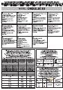
desiderata (per la scelta della corrente e dell’elettrodo vedi
tabella).
•
Iniziare l’operazione di saldatura coprendosi il viso con
l’apposita maschera.
SALDATURA TIG
- Innesco:
Appoggiare la punta dell' elettrodo sul pezzo, con leggera
pressione. Sollevare l'elettrodo di 2-3 mm con qualche istante di
ritardo, ottenendo cosi' l'innesco dell' arco con valore di corrente
corrispondente a quello impostato.
- Per interrompere la saldatura sollevare rapidamente l'elettrodo dal
pezzo.
Manutenzione:
Eventuali riparazioni dovranno essere eseguite solo
dai nostri centri autorizzati, oppure direttamente dalla DITTA
COSTRUTTRICE.
ENGLISH
OPERATING PRINCIPLE:
The welding machine manages
automatically various parameters that allow a good result of the
welding operation:
HOT START:
Generally when we start welding operation we have
some difficulties because electrode and working piece are cold.
During this phase the equipment supplies (for a small time) the
starting current with a value higher than value planed. This helps the
arc ignition and makes more stable welding process.
ARC FORCE:
During welding operations the electrode is guided by
the operator's hand, therefore the distance from the welding point is
not always the same. To avoid that electrode approaching the
welding melt creates a short circuit ,the electronic equipment
automatically increases the arc current value to eliminate that.
ANTI-STICK:
If during welding process we have a permanent short
circuit, immediately the current value decreases until the value to
allow to the electrode be removed from the melt and welding process
can proceed regularly.
THERMAL PROTECTION:
when yellow led is ignited is not possible
to carry out the welding. Signal light is switch off automatically when
temperature goes down , now it is possible to weld again. When
equipment is switch on, signal remains about 3 seconds switched on.
During this time there is a check of all electronic functions and it is
impossible to operate.
NO STOP:
Selecting the “NO STOP” function through the switch the
auxiliary regulation circuit is activated and the regulation knob does
not work. So a better welding continuity and arc features are
guaranteed. Selecting the function “BASIC MMA” through the switch,
the “NO STOP” function is deactivated and it is possible to set the
parameters that are suitable for every kind of electrode.
TIG:
used to select the desired welding procedure:
•
MMA position for welding with electrode.
•
TIG-LIFT position for TIG welding.
TIG welding is a welding procedure that exploits the heat produced
by the electric arc that is struck, and maintained, between a non-
consumable electrode (tungsten) and the piece to be welded. The
tungsten electrode is supported by a torch suitable for transmitting
the welding current to it and protecting the electrode itself and the
weld pool from atmospheric oxidation, by the flow of an inert gas
(usually argon: Ar 99.5) which flows out of the ceramic nozzle.
MACHINE FUNCTIONING CONTROL DEVICE - CONNECTION OF
THE WELDING MACHINE TO EXTERNAL POWER SOURCES:
Power supply:
The plug of the power cord must be connected to a
safe power source, single-phase + PE protection conductor. Power
source must be protected by automatic switches or fuses. It is
necessary to avoid connection with long cables and in any case their
section must me equal or higher of section of the power cord of
machine. The equipment must be connected to the electrical net by
mean of suitable switch. It must be protected against overloads (
switches protected by fuses, circuit breakers,earth leakage circuit
breakers). The wiring is to be carried out by qualified personnel only
(electricians).