Manual
Chapter 4 –
Overview and Laser Safety Setup
21
–
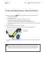
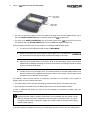
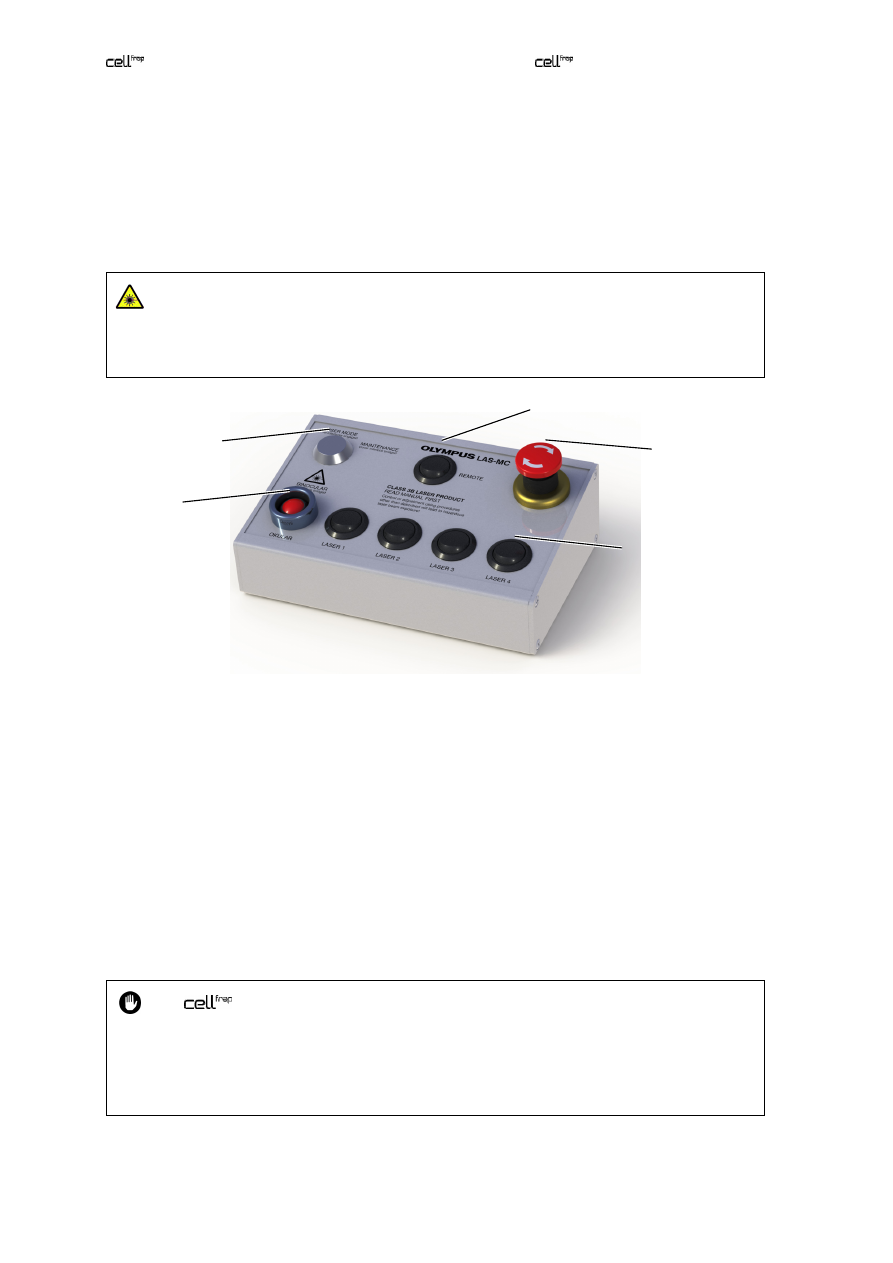
A mode lock with key to allow authorized and trained personnel to switch from standard
USER
MODE
to
MAINTENANCE
(see Chapter 5,
Modes of Operation
).
–
A red emergency interrupter that closes all safety shutters when pressed.
–
A
BINOCULAR
button to bridge the laser safety ocular shutter in
maintenance
mode so that
the specimen can be observed via ocular with laser illumination. This is not a toggle button; it
needs to be kept pressed in order to keep the laser safety shutter open.
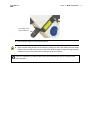
Be extremely cautious when bridging the laser safety ocular shutter by pressing the red
button! Be sure that a filter cube that quantitatively blocks reflected laser light is inserted
into the light path. Otherwise hazardous and intense laser light might exit the ocular. Set
the laser to a low intensity with the attenuator before first looking through the ocular.
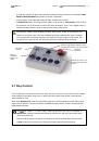
4.7
Key Control
The LAS-MC laser manual control has a lock. When the key is removed or when the lock is set to
User
mode, lifting the laser safety stage cover or opening the laser safety ocular shutter causes all laser
safety shutters to close.
When set to
Maintenance
mode, the laser safety stage cover can be lifted and the laser safety ocular
shutter can be opened – when the red button is additionally kept pressed – without causing the laser
safety shutters to close.
The
system is a Laser Safety Class 3B product and may be operated in
Maintenance
mode by trained and authorized personnel only with the trained laser safety
officer being informed.
Upon leaving the system, the person in charge has to set the LAS-MC laser manual control
to
User
mode and remove the key to protect the system against unauthorized use.
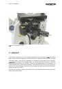
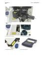
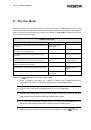
Switches for up to four TTL-
controlled high-speed laser
shutters
Button to
bridge laser
safety ocular
shutter
Mode lock
with key
Emergency
interrupter
Switch to toggle between software control
and hand switch control of TTL laser shutters