Manual
Chapter 6 –
Operating the
System
31
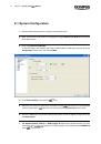
8.
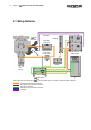
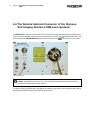
TTL Synchronization
,
FRAP Trigger OUT -> DIG I/O
. Select from the short list the TTL IN
connection at the
imaging PC front panel that is connected with the
TRIGGER
OUT
of the
control unit.
9.
Exit the software with
OK
.
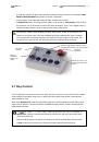
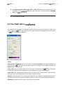
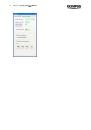
6.2
The FRAP GUI in
This interface is mainly meant for calibration purpose and for opening and closing the FRAP laser
shutter. The use of
in the context of "true" FRAP experiments is explained in the next Chapter
6.3,
in the Experiment Manage
r.
Control
Disconnected / Connected
. The box turns green and reads
Connected
if the software detects the
presence of the
controller via the serial connection. The status can be update by clicking the
Update
button on the right side.
Laser on/off
. Use this toggle button to turn the laser connected to the
(and configured
accordingly in OBS System Configuration) on or off (respectively, open or close its shutter).
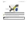
Center spot
. Click this button to move the scanner mirrors to their central position. This will set the
laser spot to the central image position if the system is aligned correctly.
Objective
. This field displays the currently active objective. The calibration needs to be performed for
each objective that is to be used for the FRAP experiments. The currently used objective is listed here.
Calibrated
. The status box turns green once the system is calibrated.