6901-170199 <05>
22
3-1
EN
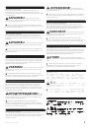
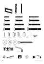
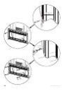
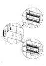
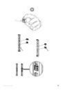
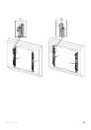
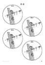
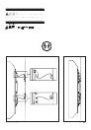
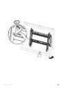
Install Brackets
1.
Determine the bolt diameter for your TV and your TV type.
Ù
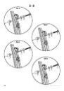
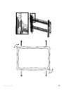
For TVs with a flat/unobstructed back, see 3-2.
Ù
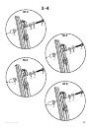
For TVs with an irregular/obstructed back, see 3-3 or 3-4.
If you need extra space to accommodate cables, recesses, or protrusions, see
an installation option (3-3 or 3-4) that uses spacers.
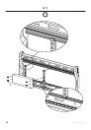
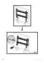
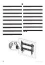
2. Ensure that the brackets are level on the back of the TV.
Standard configurations are shown. For special applications, contact Cus-
tomer Service.
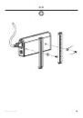
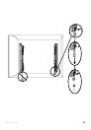
CAUTION:
Use the shortest screw and spacer
combination needed to accommodate cables, recesses, or protrusions. Using
hardware that is too long may damage your TV’s internal components.
FR
Installation des étriers
1.
Avant d’installer les supports, déterminez le diamètre des boulons
pour le type de votre téléviseur :
Ù
Pour les téléviseurs dont l’arrière est plat ou sans obstruction, consultez
l’étape 3-2
Ù
Pour les téléviseurs dont l’arrière est irrégulier ou obstrué, consultez
l’étape 3-3 ou 3-4.
Si vous avez besoin de plus d’espace à cause des câbles, des creux ou des
protubérances, consultez l’une des options d’installation (3-3 ou 3-4) util-
isant des entretoises.
2. Assurez-vous que les brides de montage sont à l’horizontale derrière
le moniteur.
Les configurations standard sont illustrées. Consultez le service à la clientèle
pour des applications particulières.
ATTENTION:
Utilisez la combinaison la plus
courte de vis et d’entretoise nécessaire pour contourner toute obstruction ou
permettre l’installation d’un moniteur dont l’arrière est incurvé. L’utilisation
de quincaillerie trop longue pourrait endommager les composantes internes
de votre moniteur.
DE
Montieren der Anschlussplatten
1.
Bestimmen Sie den Schraubendurchmesser für Ihren Fernseher und
Ihren Fernsehtyp, bevor Sie die Anschlussplatten montieren:
Ù
Bei Fernsehern mit flacher/hindernisfreier Rückseite, siehe Schritt 3-2.
Ù
Bei Fernsehern mit ungleichförmiger Rückseite mit Hindernissen, siehe
Schritt 3-3 bzw. 3-4.
Wenn Sie zusätzlichen Platz zur Unterbringung von Kabeln, Vertiefungen
oder Überständen benötigen, schauen Sie sich eine der Montageoptionen
(3-3 bzw. 3-4) an, bei denen Abstandhalter verwendet werden.
2.
Achten Sie darauf, dass die Anschlussplatten flach auf der Rückseite
des TVs anliegen.
Standardkonfigurationen sind abgebildet. Bei besonderen Installationen
kontaktieren Sie bitte den Kundendienst.
VORSICHT:
Verwenden Sie die kürzeste
Schrauben-Abstandhalter-Kombination unter Berücksichtigung jeglicher
Hindernisse bzw. einer Rückseite mit Wölbung. Die Verwendung von zu
langen Schrauben kann die inneren Komponenten Ihres TVs beschädigen.
ES
Instale los soportes
1.
Antes de instalar los soportes, determine el diámetro de los pernos
según el tipo de televisor que tiene:
Ù
Si la parte posterior del televisor es plana o no presenta obstrucciones,
continúe con el paso 3-2.
Ù
Si la parte posterior del televisor es irregular o presenta obstrucciones,
continúe con los pasos 3-3 ó 3-4.
Si necesita más espacio para cables, concavidades o protuberancias, elija una
de las opciones de instalación (3-3 ó 3-4) que utiliza separadores.
2.
Asegúrese de que los soportes estén nivelados con respecto a la parte
posterior del TV.
Se ilustran las configuraciones estándar. En caso de aplicaciones especiales,
comuníquese con el Servicio de Atención al Cliente.
PRECAUCIÓN:
Use la combinación con el
tornillo más corto y el espaciador necesaria para que no haya ningún tipo de
obstrucción o para dar lugar a una parte posterior curva. Usar equipo que sea
demasiado largo puede dañar los componentes internos del TV.
PT
Instale os suportes
1.
Antes de instalar os suportes, determine o diâmetro do parafuso da
sua TV e o tipo de TV:
Ù
Para TVs com a parte traseira plana/desobstruída, consulte a etapa 3-2.
Ù
Para TVs com a parte traseira irregular/obstruída, consulte as etapas 3-3
ou 3-4.
Se for necessário mais espaço para comportar cabos, rebaixos ou protu-
berâncias, consulte uma das opções de instalação (3-3 ou 3-4) que utiliza
espaçadores.
2.
Certifique-se de que os suportes estão nivelados na parte traseira do
TV.
As configurações padrão são mostradas aqui. Para aplicações especiais, entre
em contato com o Atendimento ao Cliente.
ATENÇÃO:
Use a combinação de menor parafuso
e espaçador necessários para eliminar obstruções ou comportar uma parte
traseira em curva. O uso de hardware muito longo pode danificar os compo-
nentes internos do TV.
NL
Plaatsing van de beugels
1.
Voordat u de beugels plaatst, dient u de boutdiameter voor uw tv en
uw tv-type te bepalen:
Ù
Voor tv’s met een vlakke achterkant zonder uitsteeksels, zie stap 3-2.
Ù
Voor tv’s met een ongelijkmatige achterkant/achterkant met uitsteek-
sels, zie 3-3 or 3-4.
Als extra ruimte nodig is voor kabels, uitsparingen of uitsteeksels, gebruik
dan een van de installatieopties (3-3 of 3-4) waarbij afstandsringen worden
gebruikt.
2.
Zorg ervoor dat de beugels vlak op de achterkant van de TV liggen.
De standaard configuraties zijn weergegeven. Voor speciale toepassingen
kunt u contact opnemen met klantenservice.
LET OP:
Gebruik de kortst mogelijke combinatie van
schroef en afstandsringetje om ruimte te creëren voor uitsteeksels of een
ronde achterkant. Gebruik van te lange schroeven kan de interne onderdelen
van uw scherm beschadigen.