Инструкция для BEST Salina White

(скачивание инструкции бесплатно)
Формат файла: PDF
Доступность: Бесплатно как и все руководства на сайте. Без регистрации и SMS.
Дополнительно: Чтение инструкции онлайн
background image

4

ausgetauscht werden müssen.

Nach der Reinigung den Fettfiltern (und/oder dem Austausch der Kohlenfilter) ist zur Rückstellung des Stundenzählers 

die Taste 

e

 (RESET) während der Anzeige des Filteralarms zu drücken.

sensibiLitÄt des gas-sensors:

Die Sensibilität des Gas-Sensors kann entsprechend den persönlichen Bedürfnissen des Benutzers verändert werden. 

Zur Veränderung dieser Ansprechempfindlichkeit muss das Gerät sich im manuellen Betriebsmodus befinden (d.h. LED 

L2 muss ausgeschaltet sein); Gegebenenfalls ist die Taste E zu drücken.

Die  Sensibilität  kann  durch  gleichzeitiges  Drücken  der Tasten 

d

 und 

e

 verändert werden. Die jeweils eingestellte 

Sensibilität wird durch die vier grünen LEDs angezeigt. Mit den Tasten 

c

(-) und 

d

(+) wird die gewünschte Sensibilität 

eingestellt (Fig.18 S). Durch Drücken der Taste 

e

 wird die “neue” Sensibilität gespeichert.

acHtung: Keine siLiKonHaLtigen produKte in der nÄHe der abZugHaube Verwenden, da diese 

den sensor bescHÄdigen KÖnnen!


Fettfilter:

 Der Fettfilter muss besonders sorgfältig gepflegt werden. Und zwar ist er regelmäßig zu reinigen, sobald 

der Fettfilteralarm auftritt. Die Anweisungen für das Vorgehen bei Filteralarm werden im Absatz Bedienung gegeben.

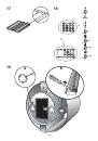
Ausbau des Fettfilters: den Griff nach außen drücken und den Filter nach unten ziehen (Abb. 3). Den Filter mit neutralem 

Reinigungsmittel waschen.


Kohlefilter:

 Wird das Gerät in der Umluftversion verwendet, muss der Kohlefilter regelmäßig ausgetauscht werden, 

sobald der Kohlefilteralarm auftritt. Die Anweisungen für das Vorgehen bei Filteralarm werden im Absatz Bedienung 

gegeben. Ausbau des Kohlefilters: zunächst den Fettfilter ausbauen, indem der Griff nach außen gedrückt und der Filter 

nach unten gezogen wird (Abb. 3); anschließend die 2 Filterhalter entfernen und den Kohlefilter herausnehmen (Abb. 

17)

 beleuchtung

:

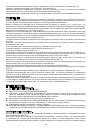
Halogenlampen. Zum Austausch der Halogenlampen Abdeckung an den Schlitzen heraushebeln (Abb. 19A). Durch 

Lampen desselben Typs ersetzen. 

acHtung: neue Lampen keinesfalls mit bloßen Händen anfassen.

Neon. Schutzabdeckung der Neonlampen durch Auseinanderdrücken der beiden Seiten entfernen (Abb. 19B); Neon

-

lampe um 90° drehen und herausziehen. Durch Lampen desselben Typs ersetzen.

ENGLISH

description


this appliance is equipped with a completely automatic system (advanced sensor control) capable to 

manage all the functions of your hood. thanks to the asc, the air in the kitchen is costantly clean and odour 

free without any manual intervention. the advanced sensor catches all sort of vapours, smokes and odours 

caused by the cooking process. the asc also captures an abnormal presence of gas. 


The unit can be found in filtering hoods or ducting hoods.
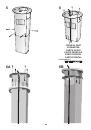


In the 

filtering version

 the air and the kitchen fumes that are conveyed by the apparatus are depurated by the 

charcoal filter and put back into the room through the small grilles of the ventilation flue (Fig. 1). ATTENTION: When using 

the filtering version, a charcoal filter and an air baffle (Fig.1A) must be used, which placed at the top of the structure, 

allows the air to recycle back into the room.


In the 

ducting version

, cooking vapours and odours are conveyed straight outside by a disposal duct which passes 

through the ceiling (Fig.2).

instaLLation


ATTENTION: 3 persons are required for proper installation; the unit should be installed by a qualified ope-

rator. also follow carefully each step of the assembly instructions, and once installation has been completed, 

make sure that the hood is firmly secured in place.


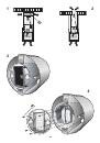
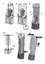
Before proceeding with assembly operations and to ensure easier manoeuvrability of the appliance, disengage the 

grease filter

: push the handle outwards and pull the filter downwards. 3).


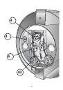
Also remove the metallic surround by removing the 4 retaining screws (Fig. 4), remove the command (Fig. 4C), 

halogen lamps (Fig. 4D) and neon (Fig. 4E) connection.


Separate the upper part of the telescopic structure from the lower part by removing the 4 retaining screws and the 

4 washers (Fig. 5).


Essential requirements for assembly: – Prepare electricity supply inside the the telescopic flue – If your appliance 

is to be installed as a Ducting version, prepare the air evacuation hole.

When installing ducting hoods, to achieve the best possible conditions use an 

air exhaust pipe

 that : is as short as 

possible, has a minimum of curves (maximum angle: 90°), is made of a material that complies with the standards (which 

vary from nation to nation) and iv) is smooth on the inside.  It is also advisable to avoid any drastic changes in pipe 

section (diameter: 150 mm).

1
2
3
4
5
6
7
8
9
10
11
12
13
14
15
16
17
18
19
20
21
22
23
24
25
26
27
28
Оглавление инструкции
  • Страница 1 из 29
    bedienungsanweisung mit montageanweisungen instructions for INSTALLATION AND use instructions pour l’INSTALLATION ET L’UTILISATION AANWIJZING VOOR GEBRUIK EN INSTALLATIE istruzioni per l’INSTALLAZIONE E L’uso INSTRUCCIONES PARA INSTALACIÓN Y USO INSTRUÇõES DE INSTALAÇÃO Y UTILIZAÇÃO РУКОВОДСТВО ПО
  • Страница 2 из 29
    DEUTSCH Monteurhinweis Bevor das Gerät montiert wird ist eine Funktionsprüfung (Lüftung und Beleuchtung) vorzunehmen. Ebenso muss die Geräteoberfläche auf ästhetische Mängel bzw. Beschädigungen der Oberflächen überprüft werden. Wenn dabei ein Defekt erkennbar ist, darf das Gerät nicht montiert
  • Страница 3 из 29
    erhaltene Block wird am Oberteil der Teleskopstruktur befestigt (Abb. 9), der bereits an der Decke befestigt worden ist (mit den zuvor abgenommenen 4 Schrauben und 4 Unterlegscheiben). Die Höhe der Teleskopstruktur wird mit Hilfe der vier Schrauben (Abb. 9) eingestellt, wobei darauf zu achten ist,
  • Страница 4 из 29
    ausgetauscht werden müssen. Nach der Reinigung den Fettfiltern (und/oder dem Austausch der Kohlenfilter) ist zur Rückstellung des Stundenzählers die Taste E (RESET) während der Anzeige des Filteralarms zu drücken. SENSIBILITÄT DES GAS-SENSORS: Die Sensibilität des Gas-Sensors kann entsprechend den
  • Страница 5 из 29
    ASSEMBLY Ducting version: Using the specific drilling template, make holes for fixing to the ceiling in the vertical part of your cooking top; observe all indications for the final positioning of the appliance. Bear in mind that one of the two axes of the template must correspond with the axis of
  • Страница 6 из 29
    C) Reduces the motor speed until reaching minimum. If pressed for 2”, the motor is switched off. If pressed for 2” when the Filter Alarm is active, the HOUR counter is reset. D) Starts the motor and increases the speed until reaching maximum E) Activates/deactivates the sensor (AUTOMATIC or MANUAL
  • Страница 7 из 29
    Pour obtenir des conditions optimales, vous devez, pour ce qui concerne la version aspirante, employer un tuyau d’évacuation qui ait: une longueur suffisante, le moins de courbes possible (l’angle maximum des courbes ne doit pas dépasser 90°), soit fait d’une matière approuvée par la loi (qui peut
  • Страница 8 из 29
    N’oubliez pas que pour la version recyclage, il faut le filtre à charbon ; vérifier s’il est déjà monté et le cas échéant installer le filtre à charbon après avoir enlevé les dispositifs de blocage filtres “A” (Fig.17).Remontez le filtre à graisse. FonCTIONNEMENT COMMANDES (Fig.18): A) Eteint et
  • Страница 9 из 29
    In de afzuigversie worden de kookluchtjes en –dampen via een afvoerpijp door de muur of het plafond rechtstreeks naar buiten geleid (Afb. 2). INSTALLATIE LET OP: Dit apparaat moet door minstens 3 personen gemonteerd worden. De installatie kan het beste overgelaten worden aan vakmensen. Bovendien
  • Страница 10 из 29
    van de afzuigkap. Tijdens deze handeling, wordt de elektrische voeding door de opening in de structuur geleid (Afb.6). Monteer de flens unit op het bovenste deel van de structuur en bevestig deze m.b.v. 2 meegeleverde bouten (Afb.6A). Monteer de onderste flens unit op het bovenste deel van de
  • Страница 11 из 29
    een neutraal schoonmaakproduct. Koolstoffilters: ingeval van een filtreerversie, moet de koolstoffilter regelmatig vervangen worden, met name wanneer het relatieve filteralarm verschijnt. Voor de aanwijzingen over het filteralarm, raadpleeg de paragraaf Bedieningselementen. Demontage van de
  • Страница 12 из 29
    rondelle tolte in precedenza). Regolate l’altezza della struttura telescopica tramite le quattro viti (Fig. 9) tenendo conto che la distanza della cappa dal piano cottura deve essere minimo 650 mm. (Fig.10). Tramite le aperture della struttura telescopica, fissare il tubo evacuazione aria alla
  • Страница 13 из 29
    Per modificare tale sensibilità, l’apparecchio deve trovarsi in modalità manuale (cioè il Led L2 deve essere spento); se cosi’ non fosse, premere il tasto E. Modificare la sensibilità premendo contemporaneamente il tasto D ed il tasto E. Verrà evidenziata la sensibilità impostata tramite i 4 led
  • Страница 14 из 29
    Desmonte el conjunto de la brida, desde la parte superior de la estructura, por medio de los 2 tornillos (Fig.6). Fije al techo la parte superior de la estructura telescópica mediante los 4 tornillos y tacos suministrados (Fig. 6); preste atención porque el emplazamiento de la estructura determina
  • Страница 15 из 29
    L2 encendido. Los led L1 indican la velocidad en funcionamiento. L1) Los 4 led VERDES indican la velocidad en funcionamiento. L2) Cuando el led está VERDE indica el modo AUTOMÁTICO. Cuando está apagado, indica el modo MANUAL. Cuando el led está ROJO, indica la Alarma de filtros. ALARMA DE FILTROS:
  • Страница 16 из 29
    e bem estável. Antes de passar às operações de montagem, para que o aparelho possa ser mais facilmente manipulado retirar o filtro anti-gordura: empurrar o manípulo em direcção ao exterior e tirar o filtro para baixo (Fig. 3). Desmontar também a moldura metálica retirando os 4 parafusos de fixação
  • Страница 17 из 29
    anteriormente retiradas). Regular a altura da estrutura telescópica através dos quatro parafusos (Fig. 9) tendo em conta que a distância do exaustor ao fogão deve ser no mínimo 650 mm. (Fig.10). Através das aberturas da estrutura telescópica, prender o tubo de evacuação do ar à flange mediante uma
  • Страница 18 из 29
    РУССКИЙ ОПИСАНИЕ Данная вытяжка снабжена полностью автоматической системой (Advanced Sensor Control), которая используется для управления всеми функциями прибора. Благодаря системе Advanced Sensor Control можно без вмешательства пользователя непрерывно поддерживать чистоту кухонного воздуха и
  • Страница 19 из 29
    Аналогичным образом надеть нижнюю трубу; передвинуть ее наверх и закрепить 4 винтами (рис. 13). Установить металлическую раму, снятую в начале установки (рис. 4). Обратить внимание на направление установки, поскольку отверстия “A” (рис. 4) должны соответствовать расположению датчика, установленного
  • Страница 20 из 29
    прибора (RESET) необходимо нажать кнопку E во время отображения аварийного сигнала фильтров. ЧУВСТВИТЕЛЬНОСТЬ ДАТЧИКА ГАЗА: чувствительность датчика может быть изменена в зависимости от потребностей. Чтобы изменить чувствительность, прибор должен находиться в ручном режиме работы (то есть индикатор
  • Страница 21 из 29
    21
  • Страница 22 из 29
    1 2 A 3 4 B 22
  • Страница 23 из 29
    4 4 4 4D 23
  • Страница 24 из 29
    5 6 FRONTAL PART VORDERTEIL PARTIE AVANT Parte frontale PARTE FRONTAL PARTE FRONTAL VOORAANZICHT ПЕРЕДНЯЯ ЧАСТЬ 6A 6B 24
  • Страница 25 из 29
    7 8 9 10 11 12 min 65 cm 25
  • Страница 26 из 29
    13 14 15 26 16
  • Страница 27 из 29
    17 18 1 2 3 4 O / S OFF/- O /OFF O /OFF 19 A B 27
  • Страница 28 из 29
    04308098/1
  • Страница 29 из 29