5
assembLY
ducting version:
Using the specific drilling template, make holes for fixing to the ceiling in the vertical part of your cooking top; observe
all indications for the final positioning of the appliance. Bear in mind that one of the two axes of the template must
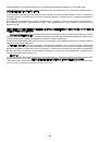
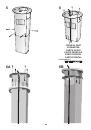
correspond with the axis of the extractor hood controls. Remove the lower flange assembly from the upper part of the
structure by undoing the 4 screws. (Fig.6B). Remove the flange assembly from the upper part of the structure by un
-
doing the 2 screws (Fig.6). Secure the upper part of the telescopic structure to the ceiling using the 4 screws and pads
supplied (Fig. 6); pay close attention since the positioning of the structure determines the final position of the extractor
hood. During this operation, pass the air air evacuation pipe inside the telescopic structure and the electricity supply
through the specific hole in the structure (Fig. 6).
Fit the flange assembly on the upper part of the structure using the 2 screws provided (Fig. 6A).
Fit the lower flange assembly on the upper part of the structure using the 4 screws provided (Fig. 6B).
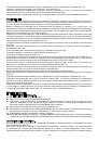
Remove the upper flue and then remove the duct by undoing the 4 screws (Fig.4B).
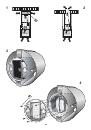
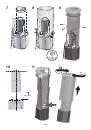
Fit the adapter flange on the air output mouth of the motor (Fig. 7).
Secure the motor unit to the lower telescopic structure, using 4 nuts and 4 washers (Fig. 8). This block should then be
secured to the upper telescopic structure (Fig. 9) previously secured to the ceiling (with the 4 screws and 4 washers
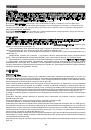
removed previously). Adjust the height of the telescopic structure using the four screws (Fig. 9) bearing in mind that the
extractor hood must be at minimum distance of 650 mm from the cooking top. (Fig.10).
Through the apertures in the telescopic structure, secure the air evacuation pipe to the adapter flange using a band
(Fig.11); the pipe and band are not supplied.
Make the electrical connection using the power supply cable.
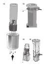
Take the upper flue and slide it onto the telescopic structure. Fasten it to the structure by turning it (Fig. 12).
Take the lower flue and insert it in the same way into the other flue; move it upwards and secure it with 4 screws (Fig.13).
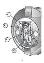
Pay special attention to the direction, since the slots (“A”. - Fig. 4) must align with the sensor mounted in the inside left
part of the extractor hood. Connect the command, halogen spotlights and neon. Refit the grease filter.
filtering Version:
Using the specific drilling template, make holes for fixing to the ceiling in the vertical part of your cooking top; observe
all indications for the final positioning of the appliance. Bear in mind that one of the two axes of the template must
correspond with the axis of the extractor hood controls.
Remove the lower flange assembly from the upper part of the structure by undoing the 4 screws. (Fig.6B).
Remove the flange assembly from the upper part of the structure by undoing the 2 screws (Fig.6).
Insert the baffle into the upper telescopic structure and secure it with 1 screw (Fig. 14). Connect a flex pipe, diameter
125 mm, securing it with a band (pipe and band not supplied).
Secure the upper part of the telescopic structure to the ceiling using the 4 screws and pads supplied (Fig. 6); pay close
attention since the positioning of the structure determines the final position of the extractor hood. During this operation,
insert the electricity supply cable through the specific hole in the structure (Fig. 6).
Fit the flange assembly on the upper part of the structure using the 2 screws provided (Fig. 6A).
Fit the lower flange assembly on the upper part of the structure using the 4 screws provided (Fig. 6B).
Remove the upper flue and then remove the duct by undoing the 4 screws (Fig.4B). Remove the control box by undoing
the 2 screws (Fig.4C).
Secure the motor unit to the lower telescopic structure, using 4 nuts and 4 washers (Fig. 8). This block should then
be secured to the upper telescopic structure (Fig. 9) previously secured to the ceiling (with the 4 screws and 4 washers
removed previously).
Adjust the height of the telescopic structure using the four screws (Fig. 9) bearing in mind that the extractor hood must
be at minimum distance of 650 mm from the cooking top (Fig.10).
Fit the adapter flange on the air output mouth of the motor (Fig. 7).
Fit the reducer above the adapter flange (Fig. 15).
Through the apertures in the telescopic structure, secure the air evacuation pipe to the reducer using a band (Fig.16);
the tube and band are not supplied. Make the electrical connection using the power supply cable.
Take the upper flue and slide it onto the telescopic structure. Fasten it to the structure by turning it (Fig. 12). Take
the lower flue and insert it in the same way into the other tube; move it upwards and secure it with 4 screws (Fig.13).
Refit the metallic surround removed prior to the installation procedure (Fig. 4).
Pay special attention to the direction, since the slots (“
a
”. - Fig. 4) must align with the sensor mounted in the inside left
part of the extractor hood. Connect the command, halogen spotlights and neon. Bear in mind that the Filtering Version
requires a charcoal filter; check to see whether already mounted. If necessary, proceed by installing the carbon filter,
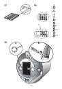
first removing the 2 filter stops “
a
” (Fig. 17).Refit the grease filter.
OPERATION
controLs (fig.18):
a)
Turns the LIGHTS on and off.
b)
Turns the NEON on and off.