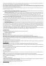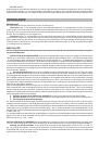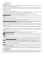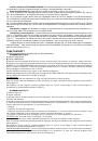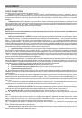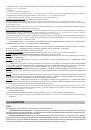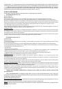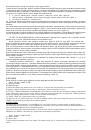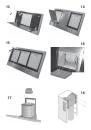
of the screws (E) as shown in Fig. 8; then, by means of the screw anchors and screws (F) provided, fix the bracket to
the ceiling in such a way that it is positioned along the axis with your hood.
4b - Connect the air outlet pipe to the air vent of the hood. - Use a flexible pipe and lock it to the air vent of the hood
with a metal hose clamp - Fig. 9 (pipe and clamp are not provided). - For exhaust hoods, turn the upper flue over so that
the air exhaust grid is in the lower section (Fig. 10).
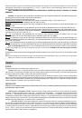
4c - Plug in the hood. Insert the extension flues setting them on the hood; extend the upper flue to the ceiling and secure
with the 2 screws (H) - Fig. 11.
INSTALLATION IN FILTERING VERSION
:
Prepare the power supply within the telescopic flues (for the electrical
connection, follow all the other instructions on the “Warnings” sheet).
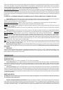
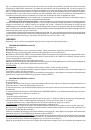
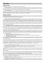
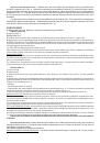
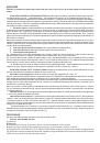
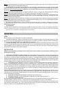
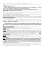
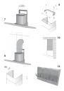
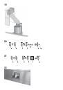
Fitting the charcoal filter
: Refer to Fig.12, Fig.13 or Fig. 14 depending on the model you have purchased. 14.
Fig. 12: Remove the grease filters: pull the handle outwards and release the filter. Then fit the charcoal filter (Fig.
16) by inserting the two charcoal filter clips in the slots and turning the filter towards the inside of the hood.
Fig. 13: Turn the glass panel gripping it from the front part of the hood. Remove the grease filter Push the catch
and turn the filter outwards Then fit the charcoal filter (Fig. 16) by inserting the two charcoal filter clips in the slots
and turning the filter towards the inside of the hood.
Fig.14: Remove the metal panels. Remove the grease filters by pushing the catch and turning the filters
outwards (Fig. 15) Then fit the charcoal filter (Fig. 16) by inserting the two charcoal filter clips in the slots and turning
the filter towards the inside of the hood.
Fixing to the wall:
for fixing to the wall refer to the instructions for the ducting version (see points 1, 2, 3), then continue
with the instructions below.
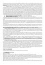
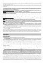
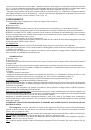
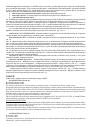
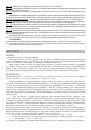
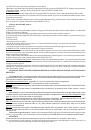
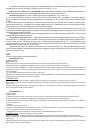
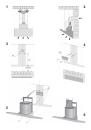
Fixing the telescopic flues:
- Adjust the width of the support bracket (D) of the telescopic flue by means of the screws
(E) as shown in Fig. 8. - Then, by means of the screw anchors and screws (F) provided, fix the bracket to the ceiling in
such a way that it is positioned along the axis with your hood. - Mount the flange on the hood in correspondence to the
air outlet point (Fig. 17). - Take the air baffle and fit a flexible pipe to it (125 mm diameter) locking it with a metal hose
clamp (pipe and clamps are not provided). Fit the air baffle to the upper flue (Fig. 18) with 4 screws.
- Connect the flexible pipe to the flange on the air vent (Fig. 19). - Plug in the hood. Insert the extension flues setting
them on the hood; extend the upper flue to the ceiling and secure with the 2 screws H (Fig. 11).
OPERATION
Depending on the model, the unit is equipped with the following controls:
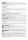
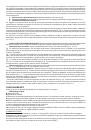
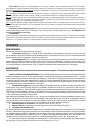
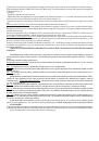
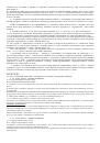
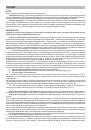
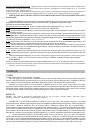
CONTROLS shown in Fig. 20
:
A)
Turns the LIGHTS off
B)
Turns the LIGHTS on.
C)
Decreases speed down to minimum speed. If pressed for 2" the motor is turned off.
D)
Activates the motor (calling the last speed used) and increases the speed until reaching maximum..
E)
FILTER ALARM/TIMER RESET: when pressing the key during display of the filter alarm (motor off) it resets the hour
counter. When pressing the key when the motor is running, the TIMER is activated and the hood will automatically be switched
off after 5 minutes.
L1)
The 4 green LEDs indicate the running speed.
L2)
When the LED is red (motor off) it indicates the FILTER ALARM. When the LED is green (flashing) it indicates that
the TIMER has been activated with the key E.
FILTER ALARM:
After 30h of operation, the LED L2 turns RED. It indicates that the grease filters need to be cleaned.
After 120h of operation, the LED L2 turns RED and flashes; It indicates that the grease filters need to be cleaned and
the charcoal filters replaced.
After cleaning the grease filters (and/or replacing the charcoal filters), restart the hour counter (RESET) by pressing the
key E during display of the filter alarm.
CONTROLS shown in Fig.21
:
A) Turns the lights off.
B) Turns the lights on.
C) Reduces the motor speed until reaching zero. If pressed for 2" when the Filter Alarm is active, the HOUR counter is
reset.
D) Drives the motor (calling the last speed used) and increases the speed until reaching maximum.
E) Activates/deactivates the sensor (AUTOMATIC or MANUAL mode). In Automatic mode the sensor is active and the
letter “A” appears on the display (L).
L) Display:
- signals the running speed
- signals Automatic mode by displaying the letter “A”. When the motor speed is changed, the running speed is displayed
flashing 3 times, and then the letter “A” reappears.
- signals the filter alarm (with motor off) by displaying the central segment for 30".
FILTER ALARM: Displayed for 30" when the motor is off: