18
English
39.
During slide cutting operation, the saw must be pushed and slided away
from the operator.
40.
Take all the possibility of residual risks in cutting operation into your
consideration, such as the laser radiation to your eyes, the inadvertent
access to moving parts on slide mechanical parts on machine and so on.
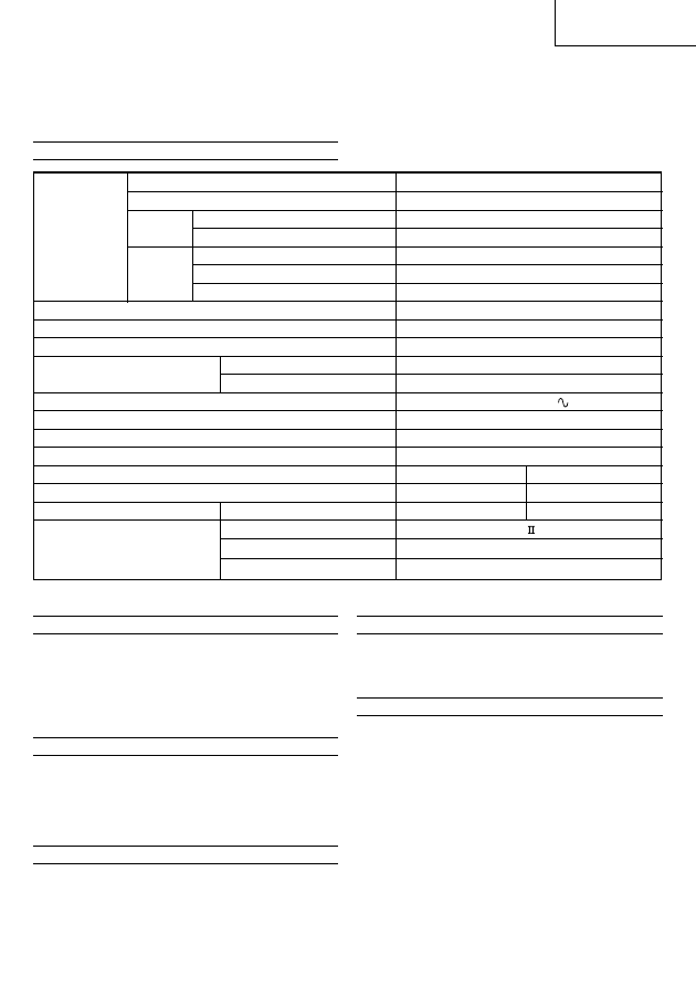
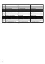
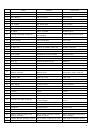
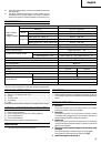
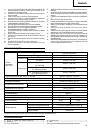
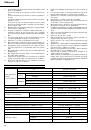
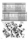
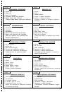
SPECIFICATIONS
0°
105 mm
×
312 mm
Miter 45°
105 mm
×
220 mm
Left 45°
68 mm
×
312 mm
Bevel
Right 45°
43 mm
×
312 mm
Bevel (Left) 45° + Miter 45°
68 mm
×
220 mm
Compound Bevel (Right) 45° + Miter (Left)
31°
43 mm
×
265 mm
Bevel (Right) 45° + Miter (Right)
45°
43 mm
×
220 mm
Saw Blade Dimensions (oD
×
iD
×
Thickness)
305 mm
×
30 mm
×
2.3 mm
Miter Cutting Angle
Right 0° – 57°, Left 0° – 46°
Bevel Cutting Angle
Right and Left 0° – 45°
Compound Cutting Angle
Bevel (Left) 0° – 45°
Miter (Left) 0° – 45°, Miter (Right) 0° – 31°
Bevel (Right) 0° – 45°
Miter (Right) 0° – 45°, Miter (Left) 0° – 31°
Voltage (by areas)*
(110 V, 230 V)
Power Input*
1520 W
No-Load Speed
4000 min
–1
Machine Dimensions (Width
×
Depth
×
Height)
595 mm
×
930 mm
×
710 mm
Model
C12LSH
C12RSH
Weight (Net)
30 kg
29 kg
Digital Display
Precision ±0.5°
Yes
No
Maximum output
Po<3 mW Class Laser Product
(Iambda)
654 nm
Laser medium
Laser Diode
Laser Marker
Max. Cutting
Capacity
Height
×
Width
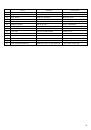
STANDARD ACCESSORIES
(1) 305 mm TCT Saw blade (mounted on tool) .................................................. 1
(2) Dust bag ........................................................................................................... 1
(3) 17 mm Box wrench ......................................................................................... 1
(4) Vise Assembly ................................................................................................. 1
(5) Holder ............................................................................................................... 1
Standard accessories are subject to change without notice.
OPTIONAL ACCESSORIES (SOLD SEPARATELY)
(1) Extension Holder and Stopper
(2) Crown molding Vise Ass'y (Include Crown molding Stopper (L))
(3) Crown molding Stopper (L)
(4) Crown molding Stopper (R)
Optional accessories are subject to change without notice.
APPLICATION
䡬
Cutting various types of aluminium sash and wood.
UNPACKING
䡬
Carefully unpack the power tool and all related items (standard accessories).
䡬
Check carefully to make certain all related items (standard accessories) are
present.
PRIOR TO OPERATION
1.
Power source
Ensure that the power source to be utilized conforms to the power
requirements specified on the product nameplate.
2.
Power switch
Ensure that the power switch is in the OFF position. If the plug is connected
to a receptacle while the trigger switch is in the ON position, the power tool
will start operating immediately, inviting serious accident.
3.
Extention cord
When the work area is removed from the power source, use an extension
cord of sufficient thickness and rated capacity. The extension cord should be
kept as short as practicable.
4.
When the power tool is prepared for shipping, its main parts are secured by
a locking pin
Move the handle slightly so that the locking pin can be disengaged.
During transport, lock the locking pin into the gear case (Fig. 3).
5.
Attach the dust bag to the main unit (Fig. 1)
* Be sure to check the nameplate on product as it is subject to change by areas.
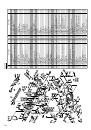
 1
1
 2
2
 3
3
 4
4
 5
5
 6
6
 7
7
 8
8
 9
9
 10
10
 11
11
 12
12
 13
13
 14
14
 15
15
 16
16
 17
17
 18
18
 19
19
 20
20
 21
21
 22
22
 23
23
 24
24
 25
25
 26
26
 27
27
 28
28
 29
29
 30
30
 31
31
 32
32
 33
33
 34
34
 35
35
 36
36
 37
37
 38
38
 39
39
 40
40
 41
41
 42
42
 43
43
 44
44
 45
45
 46
46
 47
47
 48
48
 49
49
 50
50
 51
51
 52
52
 53
53
 54
54
 55
55
 56
56
 57
57
 58
58
 59
59
 60
60
 61
61
 62
62
 63
63
 64
64
 65
65
 66
66
 67
67
 68
68
 69
69
 70
70
 71
71
 72
72
 73
73
 74
74
 75
75
 76
76
 77
77
 78
78
 79
79
 80
80
 81
81
 82
82
 83
83
 84
84
 85
85
 86
86
 87
87
 88
88
 89
89
 90
90
 91
91
 92
92
 93
93
 94
94
 95
95
 96
96
 97
97
 98
98
 99
99
 100
100
 101
101
 102
102
 103
103
 104
104
 105
105
 106
106
 107
107
 108
108
 109
109
 110
110
 111
111
 112
112
 113
113
 114
114