20
English
CAUTION
After adjusting the table insert for right angle cutting, the table insert will be
cut to some extent if it is used for bevel angle cutting.
When bevel cutting operation is required, adjust the table insert for bevel
angle cutting.
8.
Confirmation for use of sub fence (A)
WARNING
In the case of right bevel cutting, turn the sub fence (A) clockwise. Unless it
is turned clockwise, the main body or saw blade may contact the sub fence
(A), resulting in an injury.
This power tool is equipped with a sub fence (A).
In the case of direct angle cutting and left bevel angle cutting, use the sub
fence (A). Then, you can realize stable cutting of the material with a wide
back face.
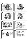
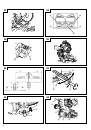
In the case of right bevel cutting, raise the sub fence (A) up as illustrated in
Fig. 11 and then turn it clockwise.
9.
Confirmation for use of sub fence (B)
WARNING
In the case of left bevel cutting, turn the sub fence (B) counterclockwise.
Unless it is turned counterclockwise, the main body or saw blade may contact
the sub fence (B), resulting in an injury.
This power tool is equipped with a sub fence (B). In the case of direct angle
cutting and right bevel angle cutting, use the sub fence (B). Then, you can
realize stable cutting of the material with a wide back face. In the case of left
bevel cutting, raise the sub fence (B) up as illustrated in Fig. 12 and turn it
counterclockwise.
10. Using an ink line
(1) Right angle cutting
Loosen the 6 mm knob bolt and contact the tip of the guard with the
workpiece.
Aligning the ink line on the workpiece with the groove of the guard, the
workpiece is cut on the ink line.
(2) Miter cutting and compound cutting (Miter cutting + bevel cutting)
Upon lowering the motor section, the lower guard is raised and the saw
blade appears.
Align the ink line with the saw blade.
CAUTION
In some arrangements when the turntable is rotated, the guard projects from
the fence surface. Loosen the 6 mm knob bolt and push the guard to the
retracted position. Never lift the lower guard while the saw blade is rotating.
When cutting at an angle to the right or more, please slide the guard to the
rear.
The guard and sub-fence (A) and sub-fence (B) will not only make contact
and adversely affect cutting accuracy, this could also result in damage to the
guard.
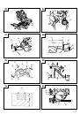
11. Position adjustment of laser line
Ink lining can be easily made on this tool to the laser marker. A switch lights
up the laser marker (Fig. 15).
Depending upon your cutting choice, the laser line can be aligned with the
left side of the cutting width (saw blade) or the ink line on the right side.
The laser line is adjusted to the width of the saw blade at the time of factory
shipment. Adjust the positions of the saw blade and the laser line taking the
following steps to suit the use of your choice.
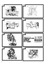
(1) Light up the laser marker and make a groove of about 5 mm deep on the workpiece
that is about 20 mm in height and 150 mm in width. Hold the grooved workpiece
by vise as it is and do not move it. For grooving work, refer to “24. Groove cutting
procedures”.
(2) Then, turn the adjuster and shift the laser line. (If you turn the adjuster
clockwise, the laser line will shift to the right and if you turn it
counterclockwise, the laser line will shift to the left.) When you work with
the ink line aligned with the left side of the saw blade, align the laser line
with the left end of the groove (Fig. 16). When you align it with the right side
of the saw blade, align the laser line with the right side of the groove.
(3) After adjusting the position of the laser line, draw a right-angle ink line on
the workpiece and align the ink line with the laser line. When aligning the
ink line, slide the workpiece little by little and secure it by vise at a position
where the laser line overlaps with the ink line. Work on the grooving again
and check the position of the laser line. If you wish to change the laser line’s
position, make adjustments again following the steps from (1) to (3).
WARNING
䡬
Make sure before plugging the power plug into the receptacle that the main
body and the laser marker are turned off.
䡬
Exercise utmost caution in handling a switch trigger for the position
adjustment of the laser line, as the power plug is plugged into the receptacle
during operation.
If the switch trigger is pulled inadvertently, the saw blade can rotate and
result in unexpected accidents.
䡬
Do not remove the laser marker to be used for other purposes.
CAUTION (Fig. 13 and Fig. 14)
䡬
Laser radiation - Do not stare into beam.
䡬
Laser radiation on work table. Do not stare into beam. If your eye is exposed
directly to the laser beam, it can be hurt.
䡬
Do not dismantle it.
䡬
Do not give strong impact to the laser marker (main body of tool); otherwise,
the position of a laser line can go out of order, resulting in the damage of the
laser marker as well as a shortened service life.
䡬
Keep the laser marker lit only during a cutting operation. Prolonged lighting
of the laser marker can result in a shortened service life.
䡬
Use of controls or adjustments or performance of procedures other than
those specified herein may result in hazardous radiation exposure.
NOTE
䡬
Perform cutting by overlapping the ink line with the laser line.
䡬
When the ink line and the laser line are overlapped, the strength and weakness
of light will change, resulting in a stable cutting operation because you can
easily discern the conformity of lines. This ensures the minimum cutting
errors.
䡬
In outdoor or near-the-window operations, it may become dificult to observe
the laser line due to the sunlight. Under such circumstances, move to a place
that is not directly under the sunlight and engage in the operation.
䡬
Do not tug on the cord behind the motor head or hook your finger, wood
and the like around it; otherwise, the cord may come off and the laser marker
may not be lit up.
䡬
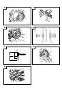
Check and make sure on a periodic basis if the position of the laser line is in
order. As regards the checking method, draw a right-angle ink line on the
workpiece with the height of about 20 mm and the width of 150 mm, and
check that the laser line is in line with the ink line [The deviation between the
ink line and the laser line should be less than the ink line width (0.5 mm)].
(Fig. 17)
12. Digital display panel (for C12LSH) (Fig. 18 and Fig. 19)
(1) Turning on the digital display switch shows 0° for both miter and bevel angle,
regardless of main unit angle.
(2) Align the main unit angle with the tilt angle (0°) and miter angle (0°) and
hold down their reset buttons for at least 0.2 second.
(3) Turning on the laser marker switch while the digital display switch is on,
lights up the laser marker. (On the C12RSH, only the laser marker switch.)
CAUTION
䡬
When operating the digital panel, have the motor head section at the top
limit position and the blade stopped.
䡬
If the figure shown on the miter angle digital display is different from the
positive stop angle (for example, 45.0°
→
45.5°, 31.6°
→
32.0°) then the positive
stop has probably deviated slightly from its correct position. If this happens,
do as follows.
(1)Move the turntable left and right with the side handle loosened, and set
the turntable to the correct position.
(2)If the figures on the display and positive stop still do not match, then
return the turntable to the 0° position. Next move the turntable left and
right with the side handle loosened as shown in Fig. 20. After setting it to
the correct position 0°, press the reset button again as shown in Fig. 18.
 1
1
 2
2
 3
3
 4
4
 5
5
 6
6
 7
7
 8
8
 9
9
 10
10
 11
11
 12
12
 13
13
 14
14
 15
15
 16
16
 17
17
 18
18
 19
19
 20
20
 21
21
 22
22
 23
23
 24
24
 25
25
 26
26
 27
27
 28
28
 29
29
 30
30
 31
31
 32
32
 33
33
 34
34
 35
35
 36
36
 37
37
 38
38
 39
39
 40
40
 41
41
 42
42
 43
43
 44
44
 45
45
 46
46
 47
47
 48
48
 49
49
 50
50
 51
51
 52
52
 53
53
 54
54
 55
55
 56
56
 57
57
 58
58
 59
59
 60
60
 61
61
 62
62
 63
63
 64
64
 65
65
 66
66
 67
67
 68
68
 69
69
 70
70
 71
71
 72
72
 73
73
 74
74
 75
75
 76
76
 77
77
 78
78
 79
79
 80
80
 81
81
 82
82
 83
83
 84
84
 85
85
 86
86
 87
87
 88
88
 89
89
 90
90
 91
91
 92
92
 93
93
 94
94
 95
95
 96
96
 97
97
 98
98
 99
99
 100
100
 101
101
 102
102
 103
103
 104
104
 105
105
 106
106
 107
107
 108
108
 109
109
 110
110
 111
111
 112
112
 113
113
 114
114