19
English
6.
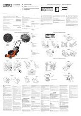
Installation
Ensure that the machine is always fixed to bench.
Attach the power tool to a level, horizontal work bench.
Select 8 mm diameter bolts suitable in length for the thickness of the work
bench.
Bolt length should be at least 40 mm plus the thickness of the work bench.
For example, use 8 mm
×
65 mm bolts for a 25 mm thick work bench.
ADJUSTING THE POWER TOOL PRIOR TO USE
CAUTION
Make all necessary adjustments before inserting the plug in the power source.
1.
Check to see that the lower guard operates smoothly
CAUTION
䡬
This slide compound miter saw is equipped with a saw head lock as safety
device.
䡬
To lower the saw head to cut, the lock must be released by pressing the
lever (A) with your thumb.
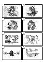
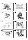
(1) When you push down the handle while pushing the lever (A), check that the
lower guard revolves smoothly (Fig. 4).
(2) Next, check that the lower guard returns to the original position when the
handle is raised.
2.
Checking the saw blade lower limit position (Fig. 5 and Fig. 6)
Check that the saw blade can be lowered 9 mm to 10 mm below the table
insert.
When you replace a saw blade with a new one, adjust the lower limit position
so that the saw blade will not cut the turntable or complete cutting cannot
be done.
To adjust the lower limit position of the saw blade, follow the procedure (1)
indicated below. (Fig. 6)
Furthermore, when changing the position of a 8 mm depth adjustment bolt
that serves as a lower limit position stopper of the saw blade.
(1) Turn the 8 mm depth adjustment bolt, change the height where the bolt
head and the hinge contacts, and adjust the lower limit position of the saw
blade.
NOTE
Confirm that the saw blade is adjusted so that it will not cut into the turntable.
3.
Lower limit position of saw blade when cutting a large workpiece
NOTE
When cutting a workpiece exceeding 107 mm in height in right-angle cutting
or 70 mm in left bevel angle cutting or 45 mm in right bevel angle cutting,
adjust the lower limit position so that the base of the motor head (Fig. 5) will
not come in contact with the workpiece.
To adjust the lower limit position of the saw blade, follow the procedure (1) shown
in Fig. 5.
(1) Lower the motor head, and turn the 8 mm depth adjustment bolt and make
adjustments so that there can be a clearance of 2 mm to 3 mm between the
lower limit position of the motor head and the top of the workpiece at the
saw blade's lower limit position where the head of the 8 mm depth adjustment
bolt contacts the hinge.
PRACTICAL APPLICATIONS
WARNING
䡬
To avoid personal injury, never remove or place a workpiece on the table
while the tool is being operated.
䡬
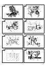
Never place your limbs inside of the line next to warning sign while the tool
is being operated. This may cause hazardous conditions (see Fig. 7).
CAUTION
䡬
It is dangerous to remove or install the workpiece while the saw blade is
turning.
䡬
When sawing, clean off the shavings from the turntable.
䡬
If the shavings accumulate too much, the saw blade from the cutting material
will be exposed. Never subject your hand or anything else to go near the
exposed blade.
1.
Tightly secure the material by vise assembly to be cut so that it does not
move during cutting
2.
Switch operation
Pulling the trigger turns the switch on. Releasing the trigger turns the switch
off.
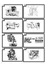
3.
Base holder adjustment (Fig. 8)
Loosen the 6 mm bolt with the 10 mm box wrench. Adjust the base holder
until its bottom surface contacts the bench or the floor surface.
After adjustment, firmly tighten the 6 mm bolt.
4.
Cutting a groove on the guard
Holder (A) has a guard (Fig. 9) into which a groove must be cut. Loosen the
6 mm knob bolt to retract the guard slightly.
After placing a suitable wooden piece to sit on the fence and the table
surfaces, fix it with the vise assembly. After the switch has been turned on
and the saw blade has reached maximum speed, slowly lower the handle to
cut a groove on the guard.
CAUTION
Do not cut the groove too quickly; otherwise the guard might become
damaged.
5.
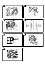
Adjusting the guard (Fig. 9)
(1) In the case of cutting at a right angle or bevel cutting:
Loosen the 6 mm knob bolt, bring the guard lightly in contact with the
materials to be cut and secure. Align the ink line with the saw blade groove
on the guard and begin operations.
(2) In the case of miter cutting or miter cutting plus bevel cutting:
Loosen the 6 mm knob bolt, move the guard to the back, making sure that it
is not sticking out from the fence surface.
6.
Using the Vise Assembly (Standard accessory) (Fig. 10)
The vise assembly can be mounted on either the left fence (Fence (B)), or the
right fence (Fence(A)), and can be raised or lowered according to the height
of the workpiece. To raise or lower the vise assembly, first loosen the 6 mm
wing bolt (A). The vise shaft has five locking grooves into which the tip of
the 6 mm wing bolt (A) is designed to fit in order to lock the vise shaft in the
desired position. To ensure that the tip of the 6 mm wing bolt (A) is properly
aligned with the desired locking groove on the vise shaft, simply align the
upper surface of the fence to either of five locking grooves on the vise shaft
surface. Therefore, the vise assembly can be attached in either of three
positions to ensure proper height adjustment.
After adjusting the height, firmly tighten the 6 mm wing bolt (A); then turn
the upper knob, as necessary, to securely attach the workpiece in position.
WARNING
Always firmly clamp or vise to secure the workpiece to the fence; otherwise
the workpiece might be thrust from the table and cause bodily harm.
CAUTION
Always confirm that the motor head does not contact the vise assembly
when it is lowered for cutting. If there is any danger that it may do so, loosen
the 6 mm wing bolt (A) and move the vise assembly to a position where it
will not contact the saw blade.
7.
Positioning the table insert (Fig. 1)
Table inserts are installed on the turntable. When shipping the tool from the
factory, the table inserts are so fixed that the saw blade does not contact
them. The burr of the bottom surface of the workpiece is remarkably reduced,
if the table insert is fixed so that the gap between the side surface of the
table insert and the saw blade will be minimum. Before using the tool,
eliminate this gap in accordance with the following procedure.
(1) Right angle cutting
Loosen the three 5 mm machine screws, then secure the left side table insert
and temporarily tighten the 5 mm machine screws of both ends. Then fix a
workpiece (about 200 mm wide) with the vise assembly and cut it off. After
aligning the cutting surface with the edge of the table insert, securely tighten
the 5 mm machine screws of both ends. Remove the workpiece and securely
tighten the 5 mm center machine screw. Adjust the right hand table insert in
the same way.
(2) Left and right bevel angle cutting
Adjust the table insert in the manner same procedure for right angle cutting.
 1
1
 2
2
 3
3
 4
4
 5
5
 6
6
 7
7
 8
8
 9
9
 10
10
 11
11
 12
12
 13
13
 14
14
 15
15
 16
16
 17
17
 18
18
 19
19
 20
20
 21
21
 22
22
 23
23
 24
24
 25
25
 26
26
 27
27
 28
28
 29
29
 30
30
 31
31
 32
32
 33
33
 34
34
 35
35
 36
36
 37
37
 38
38
 39
39
 40
40
 41
41
 42
42
 43
43
 44
44
 45
45
 46
46
 47
47
 48
48
 49
49
 50
50
 51
51
 52
52
 53
53
 54
54
 55
55
 56
56
 57
57
 58
58
 59
59
 60
60
 61
61
 62
62
 63
63
 64
64
 65
65
 66
66
 67
67
 68
68
 69
69
 70
70
 71
71
 72
72
 73
73
 74
74
 75
75
 76
76
 77
77
 78
78
 79
79
 80
80
 81
81
 82
82
 83
83
 84
84
 85
85
 86
86
 87
87
 88
88
 89
89
 90
90
 91
91
 92
92
 93
93
 94
94
 95
95
 96
96
 97
97
 98
98
 99
99
 100
100
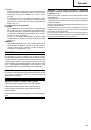 101
101
 102
102
 103
103
 104
104
 105
105
 106
106
 107
107
 108
108
 109
109
 110
110
 111
111
 112
112
 113
113
 114
114