23
English
䡬
If the 10 mm bolts are attached or detached using tools other than the 17
mm box wrench (standard accessory), excessive or improperly tightening
occurs, resulting in injury.
1.
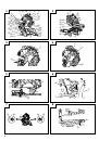
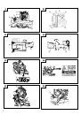
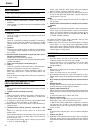
Mounting the saw blade (Fig. 33, Fig. 34, Fig. 35 and Fig. 36)
(1) Use the Phillips screwdriver to loosen the 5 mm screw fastening the spindle
cover and then turn the spindle cover.
(2) Press in spindle lock and loosen 10 mm bolt with 17 mm box wrench (standard
accessory).
Since the 10 mm bolt is left-hand threaded, loosen by turning it to the right
as shown in Fig. 35.
NOTE
If the spindle lock cannot be easily pressed in to lock the spindle, turn the 10
mm bolt with 17 mm box wrench (standard accessory) while applying
pressure on the spindle lock.
The saw blade spindle is locked when the spindle lock is pressed inward.
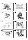
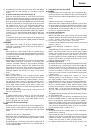
(3) Remove the bolt and washer (D)
(4) Lift the lower guard and mount the saw blade.
WARNING
When mounting the saw blade, confirm that the rotation indicator mark on
the saw blade and the rotation direction of the spindle cover (Fig. 1) are
properly matched.
(5) Thoroughly clean washer (B) and the 10 mm bolt, and install them onto the
saw blade spindle.
(6) Press in the spindle lock and tighten the 10 mm bolt by turning it to the left
by standard accessories (17 mm box wrench) as indicated in Fig. 35.
CAUTION
䡬
A dust guide is installed inside behind the hinge.
When removing or installing the saw blade, do not make contact with the
dust guide. Contact may break or chip saw blade tips.
䡬
Confirm that the spindle lock has returned to the retract position after
installing or removing the saw blade.
䡬
Tighten the 10 mm bolt so it does not come loose during operation.
Confirm the 10 mm bolt has been properly tightened before the power tool
is started.
2.
Dismounting the saw blade
Dismount the saw blade by reversing the mounting procedures described in
paragraph 1 above.
The saw blade can easily be removed after lifting the lower guard.
CAUTION
Never attempt to install saw blades except 290 mm – 305 mm in diameter.
MAINTENANCE AND INSPECTION
WARNING
To avoid an accident or personal injury, always confirm the trigger switch is
turned OFF and that the power plug has been disconnected from the
receptacle before performing any maintenance or inspection of this tool.
Report to qualified person as soon as possible, if you discover the fault of
machine including guards or blade saw.
1.
Inspecting the saw blade
Always replace the saw blade immediately upon the first sign of deterioration
or damage.
A damaged saw blade can cause personal injury and a worn saw blade can
cause ineffective operation and possible overload to the motor.
CAUTION
Never use a dull saw blade. When a saw blade is dull, its resistance to the
hand pressure applied by the tool handle tends to increase, making it unsafe
to operate the power tool.
2.
Inspecting the mounting screws
Regularly inspect all mounting screws and ensure that they are properly
tightened. Should any of the screws be loose, re-tighten them immediately.
Failure to do so could result in serious hazard.
3.
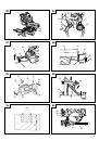
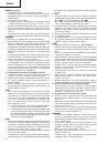
Inspecting the carbon brushes (Fig. 37)
The motor employs carbon brushes which are consumable parts. Since an
excessively worn carbon brush can result in motor trouble, replace the carbon
brushes with new ones having the same carbon brush No. shown in the
figure when it becomes worn to or near the “wear limit”. In addition, always
keep carbon brushes clean and ensure that they slide freely within the brush
holders.
4.
Replacing a carbon brushes
Disassemble the brush cap with a slotted-head screwdriver. The carbon
brushes can then be easily removed.
5.
Maintenance of the motor
The motor unit winding is the very “heart” of the power tool. Exercise due
care to ensure the winding does not become damaged and/or wet with oil or
water.
6.
Inspecting the lower guard for proper operation
Before each use of the tool, test the lower guard (Fig. 4) to assure that it is in
good condition and that it moves smoothly.
Never use the tool unless the lower guard operates properly and it is in
good mechanical condition.
7.
Storage
After operation of the tool has been completed, check that the following has
been performed:
(1) Trigger switch is in OFF position,
(2) Power plug has been removed from the receptacle,
When the tool is not in use, keep it stored in a dry place out of the reach of
children.
8.
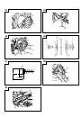
Replacement of guard
After long-term use, the blade slot in the guard may widen and require
replacement. If the blade slot should widen, replace the guard with a new
one (Fig. 38). After replacing, make a groove on it. Refer to “4. Cutting a
groove on the guard” on page 19.
9.
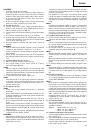
Replacement of Poly-V-Belt
The power of the motor is transmitted to the saw blade by a Poly-V-Belt.
When the Poly-V-Belt is broken or damaged, remove the belt cover by
loosening the four 5 mm screws (Fig. 2) and replace the damaged one with
the new one.
When connecting the belt on pulleys, first connect 2 or 3 teeth of Poly-V-Belt
to the grooves of the pulley (A) and pulley (B). Then turning the pulley (A)
and pulley (B), connect all 13 teeth of the belt to the pulleys (Fig. 39).
10. Lubrication
Lubricate the following sliding surfaces once a month to keep the power
tool in good operating condition for a long time.
Use of machine oil is recommended.
Oil supply points:
* Rotary portion of hinge
* Rotary portion of holder (A)
* Rotary portion of vise assembly
11. Cleaning
Periodically remove chips and other waste material from the surface of the
power tool with a damp, soapy cloth. To avoid a malfunction of the motor,
protect it from contact with oil or water.
If the laser line becomes invisible due to chips and the like adhered onto the
window of the laser marker's light-emitting section, wipe and clean the window
with a dry cloth or a soft cloth moistened with soapy water, etc.
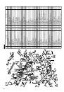
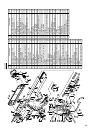
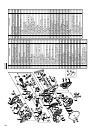
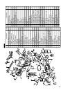
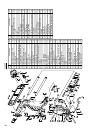
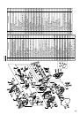
12. Service parts list
CAUTION
Repair, modification and inspection of Hitachi Power Tools must be carried
out by a Hitachi Authorized Service Center.
Especially laser device should be maintained by the authorised agent by
laser manufacturer.
Always assign the repair of laser device to Hitachi Authorised Service Center.
This Parts List will be helpful if presented with the tool to the Hitachi
Authorized Service Center when requesting repair or other maintenance.
In the operation and maintenance of power tools, the safety regulations and
standards prescribed in each country must be observed.
 1
1
 2
2
 3
3
 4
4
 5
5
 6
6
 7
7
 8
8
 9
9
 10
10
 11
11
 12
12
 13
13
 14
14
 15
15
 16
16
 17
17
 18
18
 19
19
 20
20
 21
21
 22
22
 23
23
 24
24
 25
25
 26
26
 27
27
 28
28
 29
29
 30
30
 31
31
 32
32
 33
33
 34
34
 35
35
 36
36
 37
37
 38
38
 39
39
 40
40
 41
41
 42
42
 43
43
 44
44
 45
45
 46
46
 47
47
 48
48
 49
49
 50
50
 51
51
 52
52
 53
53
 54
54
 55
55
 56
56
 57
57
 58
58
 59
59
 60
60
 61
61
 62
62
 63
63
 64
64
 65
65
 66
66
 67
67
 68
68
 69
69
 70
70
 71
71
 72
72
 73
73
 74
74
 75
75
 76
76
 77
77
 78
78
 79
79
 80
80
 81
81
 82
82
 83
83
 84
84
 85
85
 86
86
 87
87
 88
88
 89
89
 90
90
 91
91
 92
92
 93
93
 94
94
 95
95
 96
96
 97
97
 98
98
 99
99
 100
100
 101
101
 102
102
 103
103
 104
104
 105
105
 106
106
 107
107
 108
108
 109
109
 110
110
 111
111
 112
112
 113
113
 114
114