22
English
If the handle is raised while the saw blade is still rotating, the cut-off piece
may become jammed against the saw blade causing fragments to scatter
about dangerously.
When stopping the bevel cutting operation halfway, start cutting after pulling
back the motor head to the initial position.
Starting from halfway, without pulling back, causes the lower guard to be
caught in the cutting groove of the workpiece and to contact the saw blade.
CAUTION
When cutting a workpiece of 75 mm height in the left 45° bevel cutting position
or a workpiece of 50 mm height in the right 45° bevel cutting position, adjust
the lower limit position of the motor head so that the gap between the lower
edge of the motor head and the workpiece will be 2 to 3 mm at the lower
limit position (refer to “2. Checking the saw blade lower limit position”on
page 19).
19. Bevel angle fine adjustment
(1) Grip the handle on the motor head and position it at the bevel angle you
need. Temporarily tighten the clamp lever (Fig. 25).
CAUTION
If not tightened firmly enough the motor head might suddenly move or slip,
causing injuries. Be sure to tighten the motor head section enough so it will
not move.
(2) When making fine adjustments of the bevel angle, turn the knob (B) while
supporting the handle with your hand (Fig. 26).
NOTE
Turning knob (B) clockwise, allows fine adjustment of the main unit to the
left (as seen from front).
Turning knob (B) counterclockwise, allows fine adjustment of the main unit
to the right (as seen from front).
(3) After adjusting to the desired angle, tighten the clamp lever and clamp the
motor head.
CAUTION
Always check that the clamp lever is secured and the motor head is clamped.
If you attempt angle cutting without clamping the motor head, then the motor
head might shift unexpectedly causing injuries.
20. Compound cutting procedures
Compound cutting can be performed by following the instructions in 16 and
18 above. For maximum dimensions for compound cutting, refer to
“SPECIFICATIONS” table.
CAUTION
Always secure the workpiece with the right or left hand and cut it by sliding
the round portion of the saw backwards with the left hand.
It is very dangerous to rotate the turntable to the left during compound cutting
because the saw blade may come into contact with the hand that is securing
the workpiece.
In case of compound cutting (angle + bevel) by left bevel, turn the sub-fence
(B) counterclockwise, and engage in the cutting operation.
In case of compound cutting (angle + bevel) by right bevel, turn the sub-
fence (A) clockwise, and engage in the cutting operation.
21. Cutting long materials
When cutting long materials, use an auxiliary platform which is the same
height as the holder (optional accessory) and base of the special auxiliary
equipment.
Capacity: wooden material (W
×
H
×
L)
300 mm
×
45 mm
×
1300 mm, or
180 mm
×
25 mm
×
2000 mm
22. Installing the holders … (Optional accessory)
The holders help keep longer workpieces stable and in place during the
cutting operation.
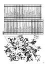
(1) As indicated in Fig. 27, use a steel square for aligning the upper edge of the
holders with the base surface.
Loosen the 6 mm wing nut. Turn a height adjustment bolt 6 mm, and adjust
the height of the holder.
(2) After adjustment, firmly tighten the 6 mm wing nut and fasten the holder
with the 6 mm knob bolt (optional accessory). If the length of Height
Adjustment Bolt 6 mm is insufficient, spread a thin plate beneath. Make sure
the end of Height Adjustment Bolt 6 mm does not protrude from the holder.
CAUTION
䡬
When transporting or carrying the tool, do not grasp the holder.
䡬
There is the danger of the holder slipping out of the base. Grasp the handle
instead of the holder.
23. Stopper for precision cutting … (Stopper and holder are optional accessory)
The stopper facilitates continuous precision cutting in lengths of 285 mm to
450 mm.
To install the stopper, attach it to the holder with the 6 mm knob bolt as
shown in Fig. 28.
24. Confirmation for use Crown molding vise, Crown molding Stopper (L) and
(R) (Optional accessory)
(1) Crown molding Stopper (L) and (R) (optional accessories) allow easier cuts
of crown molding without tilting the saw blade. lnstall them in the base
both-sides side to be shown in Fig. 29. After inserting
tighten the 6 mm knob bolts to secure the Crown molding Stoppers.
(2) The crown molding vise (B) (Optional accessory) can be mounted on either
the left fence (Fence (B)) or the right fence (Fence (A)). lt can unite with the
slope of the crown molding and vice can be pressed down.
Then turn the upper knob, as necessary, to securely attach the crown molding
in position. To raise or lower the vise assembly, first loosen the 6 mm knob
bolt.
After adjusting the height, firmly tighten the 6 mm wing bolt; then turn the
upper knob, as necessary, to securely attach the the crown molding in position
(Fig 30).
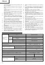
Position crown molding with its WALL CONTACT EDGE against the guide fence
and its CEILING CONTACT EDGE against the Crown molding Stoppers as
shown in Fig. 30. Adjust the Crown molding Stoppers according to the size of
the crown molding.
Tighten the 6 mm wing bolt to secure the Crown molding Stoppers. Refer to
the lower table for the miter angle.
Use the sub fence (A) to secure the crown molding more firmly (Fig. 11).
WARNING
Always firmly clamp or vise to secure the crown molding to the fence;
otherwise the crown molding might be thrust from the table and cause bodily
harm.
Do not bevel cutting. The main body or saw blade may contact the sub fence,
resulting in an injury.
CAUTION
Always confirm that the motor head (Fig. 1) does not contact the crown
molding vise ass’y when it is lowered for cutting. If there is any danger that
it may do so, loosen the 6mm knob bolt and move the crown molding vise
ass’y to a position where it will not contact the saw blade.
25. Groove cutting procedures
Grooves in the workpiece can be cut by adjusting the 6 mm depth adjustment
bolt (Fig. 32).
(1) Turn the stopper holder on the direction shown in Fig. 32.
Lower the motor head, and turn the 6 mm depth adjustment bolt by hand.
(Where the head of the 6 mm depth adjustment bolt contacts the hinge.)
(2) Adjust to the desired cutting depth by setting the distance between the saw
blade and the surface of the base (Fig. 31).
NOTE
When cutting a single groove at either end of the workpiece, remove the
unneeded portion with a chisel.
MOUNTING AND DISMOUNTING SAW BLADE
WARNING
䡬
To prevent an accident or personal injury, always turn off the trigger switch
and disconnect the power plug from the receptacle before removing or
installing a saw blade.
If cutting work is done in a state where the 10 mm bolt is not sufficiently
tightened, the 10 mm bolt can get loose, the blade can come off, and the
lower guard can get damaged, resulting in injuries.
Also, check that the 10 mm bolts are properly tightened before plugging the
power plug into the receptacle.
 1
1
 2
2
 3
3
 4
4
 5
5
 6
6
 7
7
 8
8
 9
9
 10
10
 11
11
 12
12
 13
13
 14
14
 15
15
 16
16
 17
17
 18
18
 19
19
 20
20
 21
21
 22
22
 23
23
 24
24
 25
25
 26
26
 27
27
 28
28
 29
29
 30
30
 31
31
 32
32
 33
33
 34
34
 35
35
 36
36
 37
37
 38
38
 39
39
 40
40
 41
41
 42
42
 43
43
 44
44
 45
45
 46
46
 47
47
 48
48
 49
49
 50
50
 51
51
 52
52
 53
53
 54
54
 55
55
 56
56
 57
57
 58
58
 59
59
 60
60
 61
61
 62
62
 63
63
 64
64
 65
65
 66
66
 67
67
 68
68
 69
69
 70
70
 71
71
 72
72
 73
73
 74
74
 75
75
 76
76
 77
77
 78
78
 79
79
 80
80
 81
81
 82
82
 83
83
 84
84
 85
85
 86
86
 87
87
 88
88
 89
89
 90
90
 91
91
 92
92
 93
93
 94
94
 95
95
 96
96
 97
97
 98
98
 99
99
 100
100
 101
101
 102
102
 103
103
 104
104
 105
105
 106
106
 107
107
 108
108
 109
109
 110
110
 111
111
 112
112
 113
113
 114
114